
Data storage systems

a data storage and data technology, applied in the field of module coding techniques, can solve the problem that the benefits introduced by preceding are not further availabl

Active Publication Date: 2005-06-23
GLOBALFOUNDRIES US INC
View PDF8 Cites 15 Cited by
  • Summary
  • Abstract
  • Description
  • Claims
  • Application Information

AI Technical Summary

Benefits of technology

[0015] The Applicants have recognized that it is possible to use precoding more selectively on a bit sequence to be encoded and that accordingly the use of precoding can be retained, but without the need to precode the entire input bit sequence. Thus, preceding can be applied to selected portions of the input bit sequence only. This reduces the amount of precoding that is applied (and accordingly the risk of error propagation due to the preceding), but does not eliminate the use of preceding altogether. Thus the present invention effectively uses selective or “local” preceding as compared to prior art systems that use precoding on all of the input stream (“global” preceding) or that use no preceding at all (are precoderless).
[0018] Thus, in a system where modulation coding is only applied to portions of the input bit sequence (i.e. such that after modulation coding the bit sequence contains some modulation coded bits and some bits that have not been modulation coded (i.e. that pass through the modulation coding unchanged), for example, as described in U.S. Pat. Nos. 5,604,497 and 5,784,010, incorporated herein by reference in their entirety, the preceding is preferably applied only to the modulation coded bits but not to the uncoded bits. In other words, in a particularly preferred embodiment, the criteria that governs the application of the precoding is whether at the output of the modulation encoder a bit is encoded or not, with (most preferably), encoded bits being precoded, and uncoded bits (i.e. bits that are not changed by the modulation encoder) not being precoded. This avoids the need to perform inverse preceding on unmodulation coded bits when the data is read out, thereby reducing error propagation and improving error rate performance. Thus a preferred arrangement of the present invention is a precoder that is turned on and off depending on whether it operates on random data or modulation encoded data (within a given bit sequence or block, e.g. codeword).
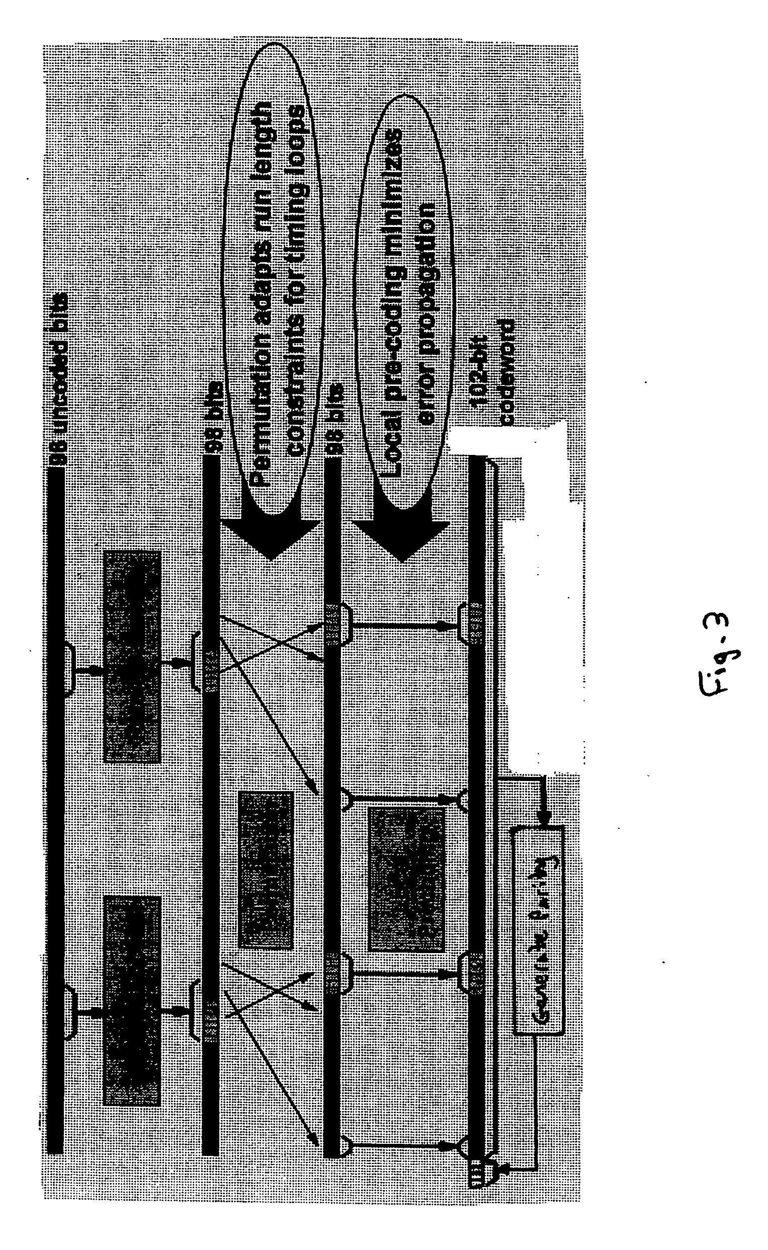
[0027] An advantage of distributing or permuting the modulation coded data bits prior to precoding is that such distribution (e.g. permutation) has been found to further aid timing recovery requirements, etc. Thus, for example, in an arrangement where only selected portions of the input bit sequence are modulation coded, in a particularly preferred embodiment of the present invention the modulation coded portions of the bit sequence are divided into plural (smaller) pieces, which pieces are then moved in position in the bit sequence so as to, e.g., space them apart and / or reorder them, i.e. such that the “pieces” of coded data are dispersed amongst the uncoded (unmodulation coded) bits also output after the modulation coding step. The preceding stage would then preferably selectively precode the modulation coded bits in the “permuted” bit sequence.
[0028] The Applicants have further recognized that moving (changing) the positions of the bits output after modulation encoding in the data sequence prior to precoding makes it possible (by appropriate selection of the bit distribution pattern) to place, e.g., given parts of the modulation coded data sequence at particular, desired locations in the data sequence. In particular, for example, the modulation coded bits can effectively be placed at the same positions in the bit sequence as seen by the precoder, irrespective, e.g., of the error correction coding and modulation coding scheme being used.
[0029] Thus, for example, by using an appropriate modulation coded bit distribution or permutation scheme, the same, unchanged, so-called “inner channel” (i.e. precoder, write / read stages, detector, and inverse precoder) arrangement can be used with different outer, error correction coding processes (i.e. such that the “inner channel” does not need to be changed to be able to operate with different outer, error correction coding processes). Thus, for example, where Reed-Solomon coding is used, the use of “permutation” as discussed above can allow the same “inner channel” (and modulation coding scheme) to be used for different Reed-Solomon code symbol sizes.
[0030] This is particularly advantageous, because although today outer Reed-Solomon error correction codes are usually based on 8-bit symbols, there is a move to the use of 10 bit Reed-Solomon symbols (as that offers a performance gain of about 0.3 dB). It would be desirable therefore to provide a system that can operate with either 8-bit or 10-bit Reed-Solomon codes. The present invention facilitates this by “permuting” the output of the modulation coding, which allows the same “inner channel” to be used with the two different Reed-Solomon symbol sizes.

Problems solved by technology

However, the benefits introduced by preceding are not further available.

Method used


Image

  • Data storage systems
  • Data storage systems
  • Data storage systems

Examples


Embodiment Construction

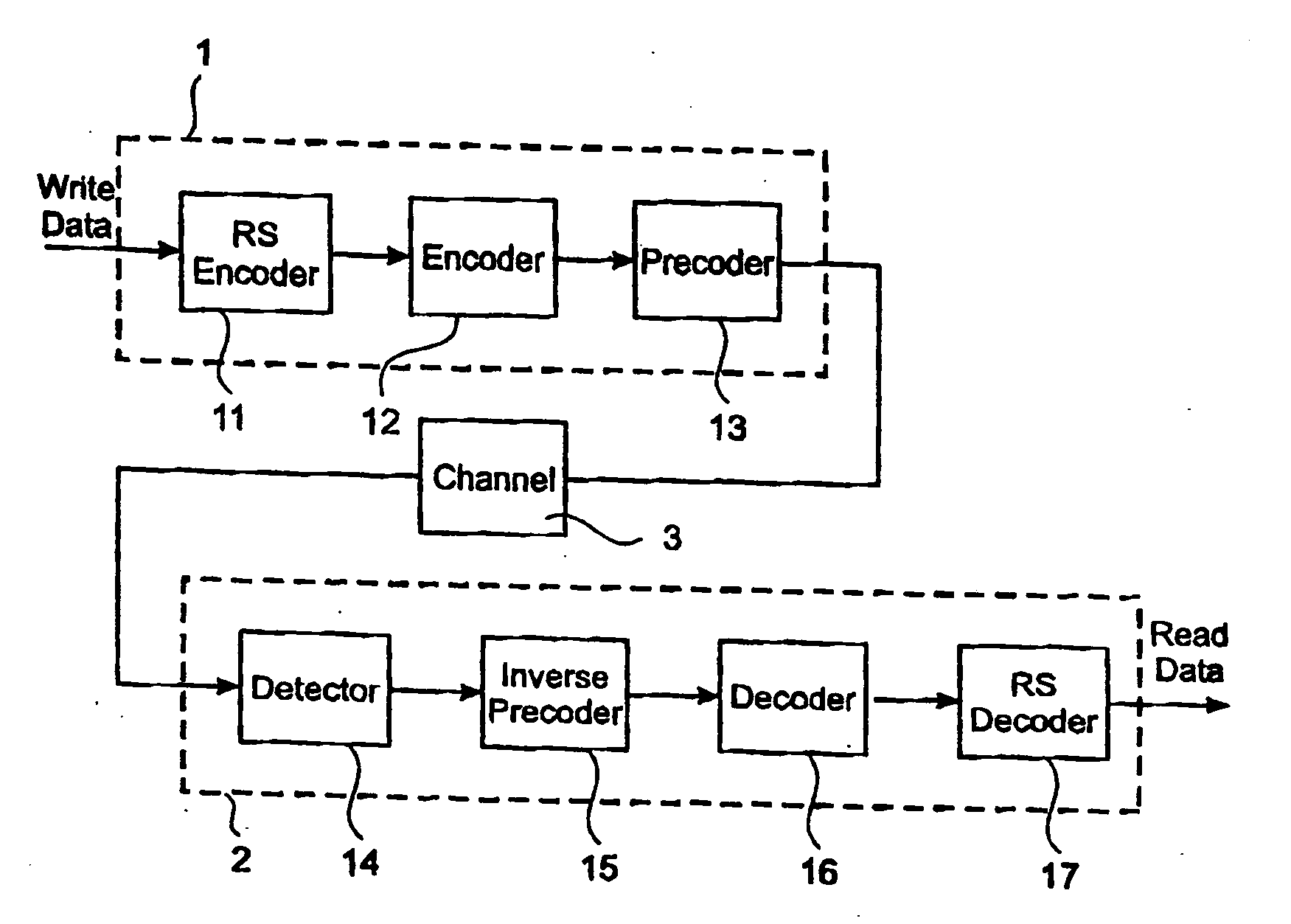
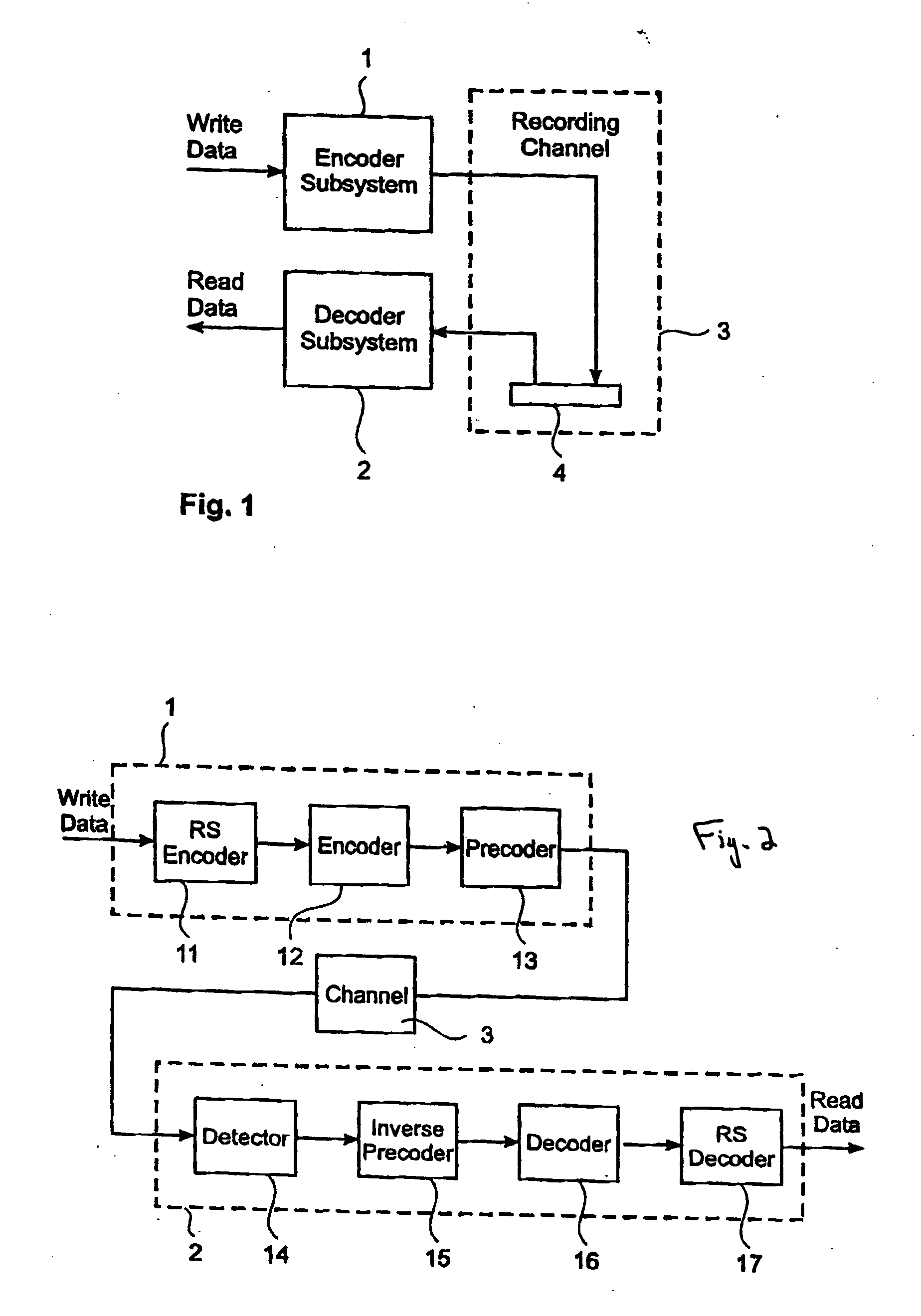
[0099]FIG. 1 is a schematic diagram of a data storage system of a type that the present invention can be applied to. The data storage system comprises an encoder subsystem 1 for encoding input write data to be written onto a storage medium 4 (which may, e.g., be in the form of a hard disk drive, a magnetic tape drive or an optical disk, etc.) of a recording channel 3, and a decoder subsystem 2 for decoding the signal detected from the recording channel 3 to produce read data (that should replicate the original, user write data). This data storage system can be implemented as desired. For example, the encoder subsystem 1 and the decoder subsystem 2 could be implemented as a single application specific integrated circuit (ASIC).

[0100]FIG. 2 shows schematically a preferred embodiment of a data storage system of the type shown in FIG. 1 that is in accordance with the present invention. In the embodiment shown in FIG. 2, the encoder subsystem 1 comprises an error correction code encoder...


PUM


Abstract

A data storage system includes an encoder subsystem comprising an error correction code encoder, a modulation encoder, and a precoder, and a decoder subsystem similarly comprising a detector, an inverse precoder, a channel decoder, and an error correction code decoder. The error correction encoder applies an error correction code to the incoming user bit stream, and the modulation encoder applies so-called modulation or constrained coding to the error correction coded bit stream. The precoder applies so-called precoding to the modulation encoded bit stream. However, this precoding is applied to selected portions of the bit stream only. There can also be a permutation step where the bit sequence is permuted after the modulation encoder before precoding is applied by the precoder. The decoder subsystem operates in the inverse manner.

Description

FIELD OF THE INVENTION [0001] The present invention relates to data storage systems and more particularly to modulation coding techniques for use when storing data in a data storage system. BACKGROUND [0002] As is known in the art, when storing data in a data storage system it is common to “code” the “raw”, original user data in some way so as to, for example, make the data storage more efficient, and less susceptible to errors. There are typically three types of coding that are employed when storing data on a storage medium. [0003] Firstly, the original data would normally be compressed in some way. This is commonly referred to as source coding. The next stage is usually to encode the compressed data to provide some form of error protection. This usually involves a coding process that adds a few bytes to the data, which bytes can then be used to detect and correct errors when the data is read out. A common example of such error correction coding (ECC) is Reed-Solomon coding. [0004]...

Claims


Application Information

Patent Timeline
IPC IPC(8): G11B20/10G11B20/14G11B20/18H03M13/00
CPCG11B20/1833G11B20/10G11B20/14G11B20/18H03M13/00
Inventor CIDECIYAN, ROY D.DHOLAKIA, AJAYELEFTHERIOU, EVANGELOS S.GALBRAITH, RICHARD L.HANSON, WELDON M.MITTELHOLZER, THOMASOENNING, TRAVIS R.
Owner GLOBALFOUNDRIES US INC
Learn More