
Endoprosthesis and Method for Manufacturing Same

a technology of endoprosthesis and manufacturing method, which is applied in the field of intraluminal endoprosthesis, can solve the problems of premature loss of mechanical integrity and stability of implants, reocclusion of stented vascular areas, and risk of restnosis, and achieves the effect of simple and inexpensive methods

Inactive Publication Date: 2010-10-14
BIOTRONIK MESS UND THERAPIEGERAETE GMBH & CO
View PDF2 Cites 7 Cited by
  • Summary
  • Abstract
  • Description
  • Claims
  • Application Information

AI Technical Summary

Benefits of technology

[0010]The feature of the present invention is to create an intraluminal endoprosthesis which prevents restenosis of the stented vessel due to neointima formation and ensures integrity over a longer period of time. Furthermore, this object consists of providing a simple and inexpensive method for manufacturing an intraluminal endoprosthesis.

Problems solved by technology

After insertion of a stent into a vessel, there is a risk of a restenosis, i.e., reocclusion of the stented vascular area, because of various processes, e.g., coagulation of body fluid or occlusion in this area caused by neointima formation due to a change in flow or an inflammation process.
Based on inhomogeneities in the material, however, locally accelerated corrosion may occur with base metals in particular such as magnesium, resulting in premature loss of mechanical integrity and stability of the implant.
Furthermore, bacterial colonization may occur on the surfaces of implants, possibly serving as a source of infection and even leading to disturbances in coagulation processes in the case of stents, in particular leading to fibrin deposits and thromboses.
Another disadvantage of implants made of lightweight metals in particular is the lack of radiopacity, which prevents effective tracking and follow-up monitoring of the implantation process.
However, the composition defined in the publication cited above is not suitable as the base body material or coating material for intraluminal endoprostheses because it has toxic or potentially toxic components with Al2O3 and the Cu, Ge, Te, Cr and F compounds listed.
Another problem with a stented vessel is that degradable, i.e., biodegradable, stents may undergo a loss of integrity too soon due to initial degradation proceeding too quickly.
Furthermore, such medical implants tend to develop bacterial contamination due to their method of use or to a predisposition of a specific patient group, endangering the patient and necessitating repeat surgery / antibiotic therapy.

Method used


Image

  • Endoprosthesis and Method for Manufacturing Same
  • Endoprosthesis and Method for Manufacturing Same
  • Endoprosthesis and Method for Manufacturing Same

Examples


example 1

[0039]For production of a stent, a melt is first prepared from a mixture of pulverized polyphosphate and additives having a composition comprising approximately 87 wt % water-insoluble phosphate glass with a P2O5 content of approximately 65-70 wt % and 13 wt % silver iodide, and the thin-walled tube 1 shown in cross section in FIG. 1 is extruded with an inside diameter r of approximately 5 mm and a wall thickness of 0.7 mm, for example. This tube can be drawn out further manually or in a device 10 to form a tube with even thinner walls of a suitable wall thickness d, e.g., a wall thickness d of approximately 150 μm, if necessary, with a suitable temperature program, e.g. by heating over a Bunsen burner until the material becomes drawable. The direction of pulling 11 in the pulling device 10 runs in the direction of the longitudinal axis of the tube. According to the properties typical of the tube material, a suitable stent cutting pattern (design) is drafted with the help of a compu...

example 2

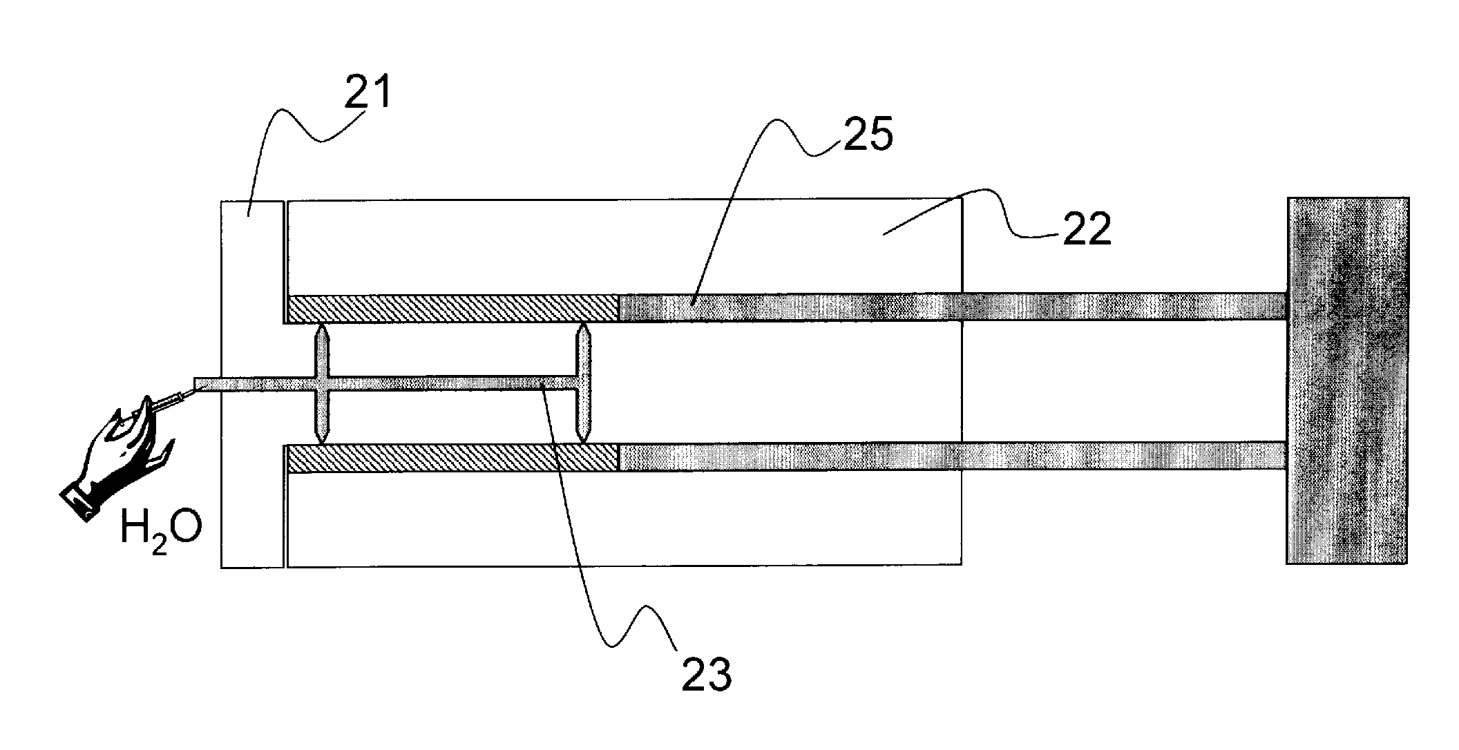
[0040]In a suitable injection molding device with the molded parts 21 and 22 stuck one inside the other as illustrated in FIGS. 2 and 3, a thin-walled tube (hollow cylinder) is shaped from an inventive Sorel cement mixture having a low water content. The hollow cylinder is formed by the hollow cylindrical cavity area 24, which is created between the hollow cylindrical molded part 22 (with a bottom) and the double-cylindrical molded part 21. The Sorel cement mixture is arranged together with additives containing polyphosphates and / or other radiopaque and / or active pharmaceutical substances and / or substances which improve the mechanical properties, e.g., pharmacologically active substances of the substance classes listed above embedded in biopolymers, are arranged in the cavity area 24. By injection of water (H2O) and / or a solution of additives (e.g. MgCl2 solution) into one or more injection channel systems (reference numerals 23 and 23′ in FIGS. 2 to 3), additives are added to the t...

example 3

[0041]In a device according to FIG. 4, a homogenized mixture of powdered anhydrous constituents having the inventive stoichiometry consisting, for example, of approximately 55 wt % of a mixture of MgO, MgCl2 (anhydrous), MgI, (anhydrous) mixture according to formula 1 and a water-insoluble polyphosphate with a P2O5 content of approximately 70 wt % is compressed at a pressure of approximately 100 kg / cm2 (or more) with the help of the tube ram 25 in the tubular cavity 24 formed by the molds 21 and 22 and / or is sintered at temperatures up to approximately 450° C. and then mixed with purified water or a salt solution until the Sorel cement is formed or solidified by subsequent heating and / or moistening to form a stable stent base body. The injection molding device in FIG. 4 corresponds in design to the device shown in FIGS. 2 and 3 except for the tube ram 25.

[0042]It will be apparent to those skilled in the art that numerous modifications and variations of is the described examples and ...


PUM


Abstract

The invention relates to intraluminal endoprosthesis, preferably a stent consisting essentially of a base body and optionally a coating covering the surface of the base body at least partially. The invention is characterized in that the base body and / or the coating has at least one compound from the group of polyphosphates, magnesium oxyhalides, preferably Sorel cement. Furthermore, a method is described for manufacturing such an intraluminal endoprosthesis.

Description

CROSS-REFERENCE TO RELATED APPLICATIONS[0001]This application claims benefit of priority to German patent application number DE 10 2008 040 791.7, filed on Jul. 28, 2008; the contents of which are herein incorporated by reference in their entirety.FIELD OF THE INVENTION[0002]The invention relates to an intraluminal endoprosthesis, preferably a stent.BACKGROUND OF THE INVENTION[0003]Endoprostheses are prostheses and implants that remain permanently in the body. Stents (vascular supports) are especially important representatives of the intraluminal endoprostheses. Stents are endovascular prostheses, which may be used for treatment of stenoses (vascular occlusions). They have a tubular or hollow cylindrical base body, preferably consisting of webs folded in a zigzag or meandering pattern, running essentially in the circumferential direction, as supporting elements and also webs running longitudinally connecting these supporting elements as connecting struts. The base body may be provid...

Claims


Application Information

Patent Timeline
IPC IPC(8): A61F2/82
CPCA61L31/02A61L31/082
Inventor ROHDE, ROLAND
Owner BIOTRONIK MESS UND THERAPIEGERAETE GMBH & CO
Learn More