
Modular, stackable, geothermal block heat exchange system with solar assist

a geothermal block and solar energy technology, applied in indirect heat exchangers, lighting and heating apparatuses, greenhouse gas reduction, etc., can solve the problems of increasing fluid transfer pumping costs and increasing installation costs, and achieve the effect of reducing installation costs and small above-ground surface area footprin

Inactive Publication Date: 2010-10-14
STOJANOWSKI JOHN
View PDF17 Cites 11 Cited by
  • Summary
  • Abstract
  • Description
  • Claims
  • Application Information

AI Technical Summary

Benefits of technology

[0014]It is therefore, an object of the present invention to provide an improved ground-source thermal exchange system that can be more widely used based on the combination of reduced installation cost and the relatively small above ground surface-area footprint required.
[0015]In accordance with this invention, there is provided a system composed of stackable, geothermal blocks, which can be assembled at the installation site. The blocks are either pre-formed containers that can be filled with material of high thermal capacity or non-containerized blocks cast from such material. By stacking the blocks, one upon another in a relatively shallow borehole, the need for expensive borehole drilling equipment currently used to drill deep wells is eliminated. Within the blocks, stacked one upon another and aligned, is at least one pair of passageways in the form of a U-shape in which a thermal transfer loop is placed; sections of the loop are helically wound to increase the total thermal transfer area. Multiple U-shape pairs of passageways within the stacked blocks, each having a loop, can be used in a single system. It is understood that a single passageway is possible in the present invention although the thermal transfer efficiency would be greatly reduced. Thermal transfer fluid, either a refrigerant or an aqueous solution, is circulated through the loop, or loops, to provide heating / cooling to an external load.
[0016]The modular design of the relatively shallow borehole system results in a low cost of installation because the stackable blocks, particularly those of the containerized design, can be filled at the installation site. Also, the need for expensive drilling, excavation or other specialized equipment and the associated high, skilled labor cost, is reduced. At any site, multiple installations of the system can be implemented and operated independently or connected in series / parallel arrangements.
[0017]The heating efficiency of existing geothermal systems, as measured by Coefficient of Performance (COP), usually range in COP values from 2 to 5. A COP of 2 corresponds to an efficiency of 200% in comparison with fossil fuel systems. The average heating COP is more likely to be about 3.5 for the entire heating season. The reason for this is the variance of ground temperatures surrounding the ground loops. There is a seasonal influence on this variance as well as a heating system usage component determined primarily by the ground loop design and size. A system that has a minimum ground loop size may effectively be “short-looped”, resulting in lower COP when outside temperatures are at their lowest values. Increasing the loop length during installation mitigates this lowering of efficiency but the increased installation cost and increased fluid transfer pumping costs are a negative consequence.
[0018]The modular, stackable, geothermal block system disclosed herein can be supplemented with a solar hot water collector system. The helically wound ground loop is enclosed within a thermally conductive conduit within stacked blocks that can be sealed and either filled with a conductive grout material or a fluid, such as a solar transfer fluid. A solar thermal collector system, used for hot water heating or to supply domestic hot water, or both, can circulate some of its hot water in the conduit space surrounding the ground loop. This would result in a significant increase in seasonal COP for the geothermal system and would reduce the size, and therefore the cost, of the ground loop system needed. It could reduce the size of the geothermal heat pump required, also reducing the installation cost. Since the ground loop is not in direct physical contact with the surrounding ground, most of the thermal energy supplied by the solar hot water collector system would be absorbed by the loop and the high thermal mass of the modular, stackable blocks. In addition, not being in direct contact with the surrounding ground lessens that probability of damage to the ground loop from abrasion with rocks and pebbles. No additional storage tank would be needed to store the solar thermal transfer fluid for the geothermal system.

Problems solved by technology

Increasing the loop length during installation mitigates this lowering of efficiency but the increased installation cost and increased fluid transfer pumping costs are a negative consequence.

Method used


Image

  • Modular, stackable, geothermal block heat exchange system with solar assist
  • Modular, stackable, geothermal block heat exchange system with solar assist
  • Modular, stackable, geothermal block heat exchange system with solar assist

Examples


Embodiment Construction

[0030]Within the drawings which describe the preferred embodiments of the present invention, like parts are identified with the same numerals.

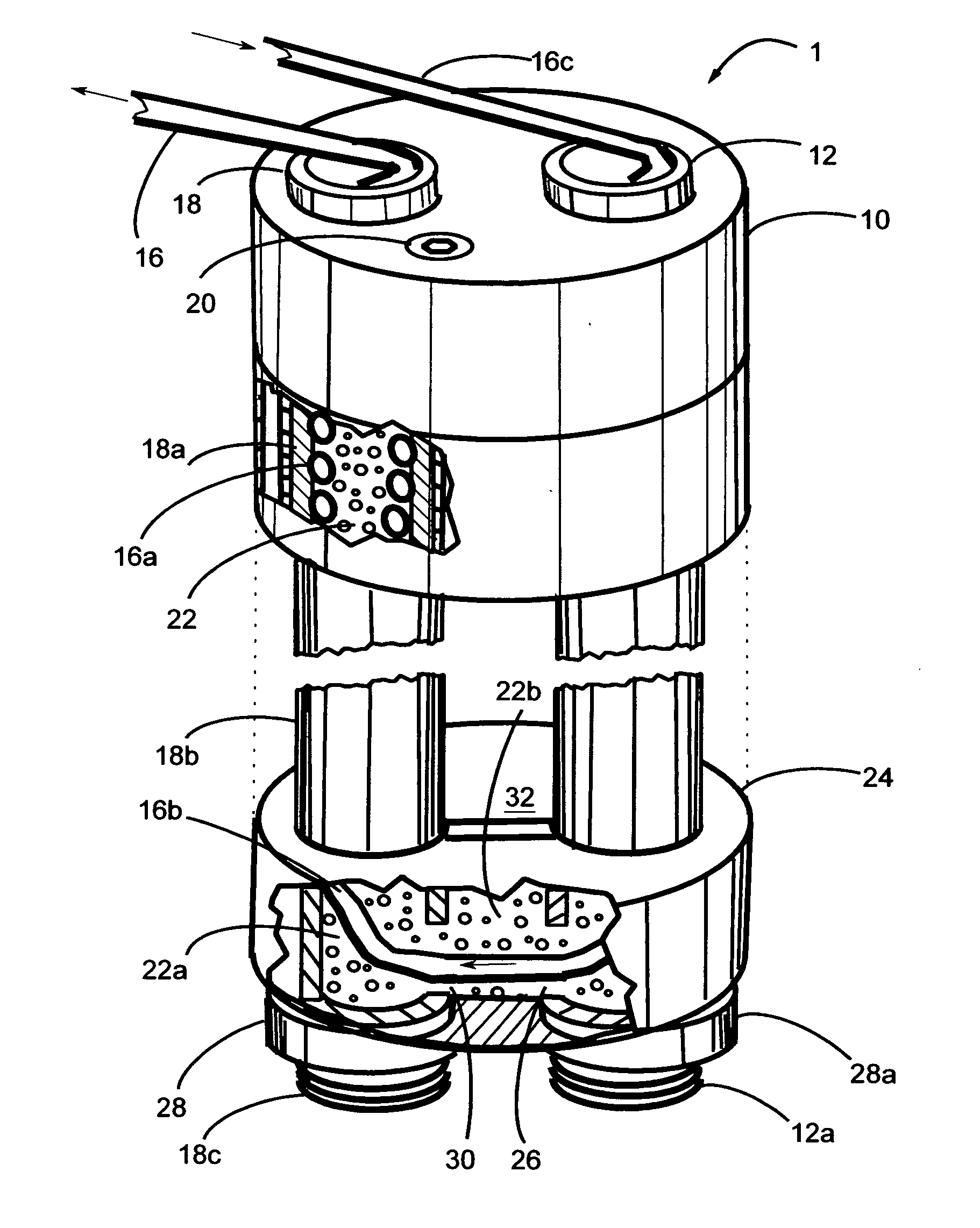
[0031]FIG. 1 illustrates the position of the various elements of the modular, stackable, geothermal block heat exchange system 1 in relation to each other and as it would be assembled in a subsurface environment. The order of description of the elements will closely parallel the sequence of the preferred method of assembly of the system.

[0032]Thermally conductive tubing 16, contains two helically coiled segments of equal length separated by centrally located uncoiled section 16b. Both ends of the tubing, 16 and 16c, are also uncoiled. One end of the tubing is inserted into the distal, threaded end of a thermally conductive tube 18c and drawn through until the coiled section is totally surrounded by the tube 18. As the tubing is drawn through the tube, a thermally conductive grout 22a is inserted so that any space between the tubing coils and b...


PUM


Abstract

A modular, stackable, geothermal block system for use as a subterranean or submarine heat exchanger in a geothermal energy system which provides a heating / cooling means to an external load. The stackable blocks, which can be filled with a fluid and / or material of generally high heat retention characteristics or precast in such material, contain one or more continuous passageways that extend from the top face of each block through the opposing face, through which a rigid structural heat exchange tube, fabricated from material of high thermal conductivity, is placed. The blocks are stacked one upon another and slidably mounted on the tube(s). Each tube contains a helically wound, thermal transfer tubing comprising one leg of a U-shape configured loop. Each stackable block can contain multiple paired passageways permitting more than one U-shape loop within the system. The system can interface with a solar thermal collector system.

Description

CROSS-REFERENCE TO RELATED APPLICATIONS[0001]This application is a Continuation-In-Part application which claims benefit of co-pending U.S. patent application Ser. No. 12 / 383,270 filed Mar. 23, 2009, entitled “Modular, Stackable, Geothermal Block System” which is hereby incorporated by reference.FEDERALLY SPONSORED RESEARCH[0002]Not ApplicableSEQUENCE LISTING OF THE PROGRAM[0003]Not ApplicableBACKGROUND OF THE INVENTION[0004]The present invention relates to the improvement of the transfer of thermal energy to and from subsurface and submarine environments, with supplemental solar heating capability, to be utilized by any heating / cooling system as well as any power generating system that could exploit a temperature differential within a moving fluid.[0005]Increasing awareness of the limited supply of fossil fuel reserves has raised interest in alternative energy sources. Cost conscious consumers have expressed interest in solar power and wind power alternative energy sources to suppl...

Claims


Application Information

Patent Timeline
IPC IPC(8): F24J3/08
CPCF28D20/0056Y02E10/10Y02E60/142F24J3/086F24J2/42F24J3/083Y02E70/30F24S90/00F24T10/15F24T10/30Y02E10/40Y02E60/14
Inventor STOJANOWSKI, JOHN
Owner STOJANOWSKI JOHN
Learn More