Receiving apparatus and time correction method for receiving apparatus

a technology of receiving apparatus and time correction method, which is applied in the direction of generating/distributing signals, data switching networks, instruments, etc., can solve the problems of not helping to achieve the object of time synchronization, still susceptible to the variation of delay time, etc., and achieve the effect of high accuracy, time correction, and minimizing the adverse effect of a variation of delay incurred by the sync pack

Inactive Publication Date: 2010-09-30
SONY CORP
View PDF6 Cites 23 Cited by
  • Summary
  • Abstract
  • Description
  • Claims
  • Application Information

AI Technical Summary

Benefits of technology

[0022]It is desirable to minimize an adverse effect of a variation in a delay, which is incurred by a sync packet, in a case where the sync packet is used to correct a time indicated by a clock unit.
[0032]The delay time of a sync packet sent over an asynchronous network includes a fixed element and a varying element. A period during which the cumulative summation value of magnitudes of jitters is the minimum value is a period during which a stable state in which the delay time of the sync packet includes only the fixed element is attained, and during which the delay time of the sync packet takes on the minimum value of delay times. Therefore, when the time indicated by the clock unit is rewritten and corrected with the compensated time during the period, the time can be corrected more highly precisely.
[0034]The delay time of a sync packet sent over an asynchronous network includes a fixed element and a varying element. During a period during which a magnitude of a jitter falls within the minimum-value range, a nearly stable state in which the varying element of the delay time of a sync packet is small is attained. Therefore, when the time indicated by the clock unit is rewritten and corrected with the compensated time during the period, the time can be corrected more highly precisely.
[0036]The delay time of a sync packet sent over an asynchronous network includes a fixed element and a varying element. During a period during which the cumulative summation value of magnitudes of jitters is the minimum value, a stable state in which the delay time of the sync packet includes only the fixed element is attained, and the delay time of the sync packet takes on the minimum value of delay times. Therefore, when the time indicated by the clock unit is rewritten and corrected with the compensated time during the period, the time can be corrected more highly precisely.
[0038]The delay time of a sync packet sent over an asynchronous network includes a fixed element and a varying element. During a period during which a magnitude of a jitter falls within the minimum-value range, a nearly stable state in which the varying element of the delay time of the sync packet is small is attained. Therefore, when the time indicated by the clock unit is rewritten and corrected with the compensated time during the period, the time can be corrected more highly precisely.
[0039]According to another embodiment of the present invention, when the time indicated by the clock unit is corrected by utilizing a sync packet, the delay time of the sync packet is estimated based on magnitudes of jitters. The transmitting time is compensated for the estimated value and thus corrected. Therefore, an adverse effect of a variation in a delay incurred by the sync packet can be minimized, and time synchronization can be highly precisely achieved with respect to a transmitting apparatus.

Problems solved by technology

However, the time synchronizing processing of rewriting the time (counter value) of the clock unit 40 with the transmitting time (counter value) represented by time stamp data contained in a received sync packet is still susceptible to the variation in a delay time.
Therefore, measuring the delay time does not help accomplish the object of time synchronization.

Method used


Image

  • Receiving apparatus and time correction method for receiving apparatus
  • Receiving apparatus and time correction method for receiving apparatus
  • Receiving apparatus and time correction method for receiving apparatus

Examples


first embodiment

1. First Embodiment

Example of the Configuration of a Receiving Apparatus

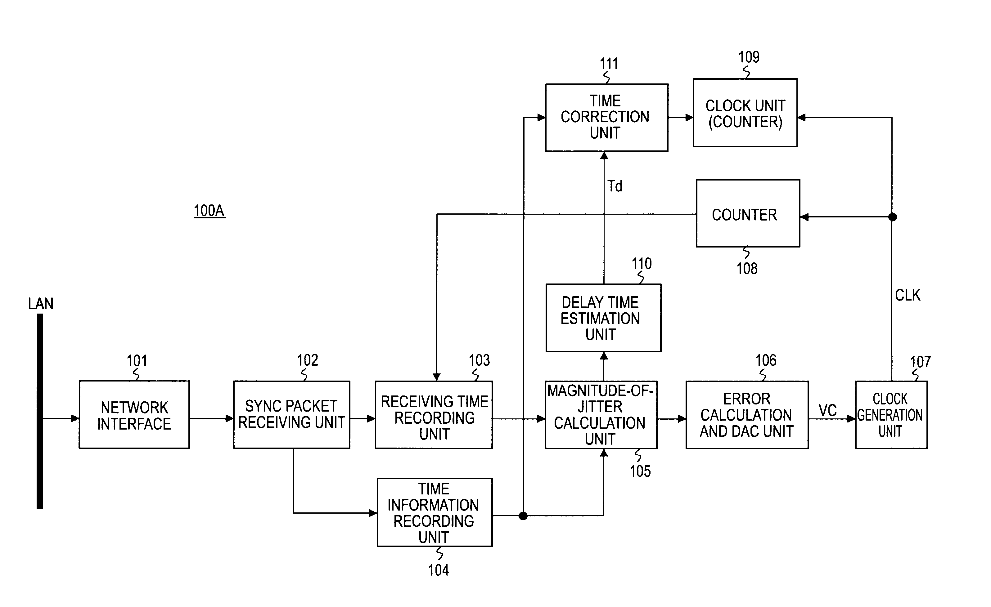
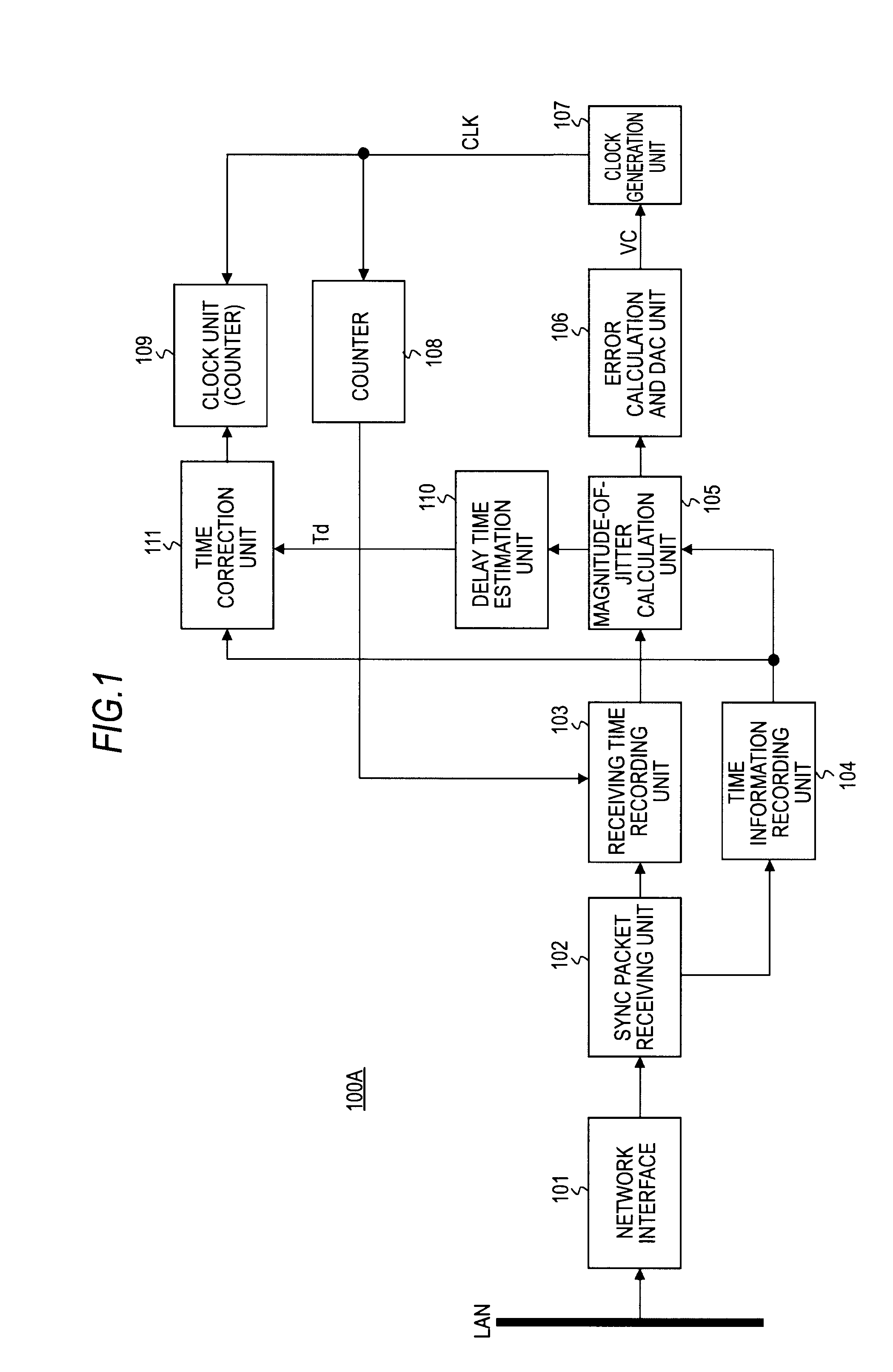
[0064]FIG. 1 shows an example of the configuration of a receiving apparatus 100A in accordance with the first embodiment of the present invention. For brevity's sake, only a portion of the receiving apparatus 100A relating to time synchronization is shown in FIG. 1.

[0065]The receiving apparatus 100A includes a network interface 101, a sync packet receiving unit 102, a receiving time recording unit 103, and a time information recording unit 104. The receiving apparatus 100A further includes a magnitude-of-jitter calculation unit 105, an error calculation and digital-to-analog conversion (DAC) unit 106, a clock generation unit 107, a clock unit (counter) 109, a counter 108, a delay time estimation unit 110, and a time correction unit 111.

[0066]The clock unit 109 outputs time information. The clock unit 109 includes a counter that counts up responsively to a clock CLK generated by the clock generation unit 107. The...

second embodiment

2. Second Embodiment

Example of the Configuration of a Receiving Apparatus

[0105]FIG. 6 shows an example of the configuration of a receiving apparatus 100B in accordance with the second embodiment of the present invention. Even in FIG. 6, similarly to FIG. 1 showing the receiving apparatus 100A, only a portion of the receiving apparatus 100B relating to time synchronization is shown for brevity's sake. In FIG. 6, the same reference numerals are assigned to components identical to those shown in FIG. 1. An iterative description will be omitted.

[0106]The receiving apparatus 100B includes a network interface 101, a sync packet receiving unit 102, a receiving time recording unit 103, and a time information recording unit 104. The receiving apparatus 100B further includes a magnitude-of-jitter calculation unit 105, an error calculation and DAC unit 106, a clock generation unit 107, a clock unit (counter) 109, a counter 108, a delay time estimation unit 112, and a time correction unit 113.

[...

third embodiment

3. Third Embodiment

Example of the Configuration of a Receiving Apparatus

[0151]FIG. 11 shows an example of the configuration of a receiving apparatus 100C in accordance with the third embodiment of the present invention. Even in FIG. 11, similarly to FIG. 1 and FIG. 6 showing the receiving apparatuses 100A and 100B respectively, only a portion of the receiving apparatus 100C relating to time synchronization is shown for brevity's sake. In FIG. 11, the same reference numerals are assigned to components identical to those shown in FIG. 1. An iterative description will be omitted.

[0152]The receiving apparatus 100C includes a network interface 101, a sync packet receiving unit 102, a receiving time recording unit 103, and a time information recording unit 104. The receiving apparatus 100C further includes a magnitude-of-jitter calculation unit 105, an error calculation and DAC unit 106, a clock generation unit 107, a clock unit (counter) 114, a delay time estimation unit 110, and a time ...


PUM


Abstract

A receiving apparatus includes: a clock unit that outputs time information; a synchronizing (sync) packet receiving unit that receives a sync packet which contains transmitting time information and which is sent from a transmitting apparatus over an asynchronous network; a magnitude-of-jitter calculation unit that calculates as a magnitude of a jitter a difference between a first difference, which is a difference between the receiving times of two adjoining sync packets received by the sync packet receiving unit, and a second difference which is a difference between the transmitting times of the two sync packets; a delay time estimation unit that obtains the delay time of the sync packet on the basis of magnitudes of jitters calculated by the magnitude-of-jitter calculation unit; and a time correction unit that compensates the transmitting time of the sync packet, which is received by the sync packet receiving unit, on the basis of the delay time of the sync packet, which is obtained by the delay time estimation unit, so as to obtain a compensated time, and rewrites and corrects the time of the clock unit with the compensated time.

Description

BACKGROUND OF THE INVENTION[0001]1. Field of the Invention[0002]The present invention relates to a receiving apparatus and a time correction method for the receiving apparatus. More particularly, the present invention is concerned with a receiving apparatus that corrects a time indicated by a clock unit by utilizing a synchronizing packet sent from a transmitting apparatus over an asynchronous network.[0003]2. Description of the Related Art[0004]In the past, a receiving apparatus including a clock unit which outputs time information has been known to correct a time indicated by the clock unit by utilizing a synchronizing packet sent from a transmitting apparatus over an asynchronous network.[0005]FIG. 17 shows an example of the configuration of a receiving apparatus 400 in accordance with a related art. In FIG. 17, a portion of the receiving apparatus relating to time synchronization described in JP-A-2004-304809 is schematically shown. In the receiving apparatus 400, a synchronizin...

Claims


Application Information

Patent Timeline
Patent Type & Authority Applications(United States)
IPC IPC(8): G06F15/16H04L7/00H04L12/70
CPCH04J3/0682H04L1/205H04J3/0685H04J3/0664H04J3/0667
Inventor MATSUNAGA, OSAMU
Owner SONY CORP
Why Eureka
Try Eureka