Image processing device, photographing device, reproducing device, integrated circuit, and image processing method
- Summary
- Abstract
- Description
- Claims
- Application Information
AI Technical Summary
Benefits of technology
Problems solved by technology
Method used
Image

Examples
first embodiment
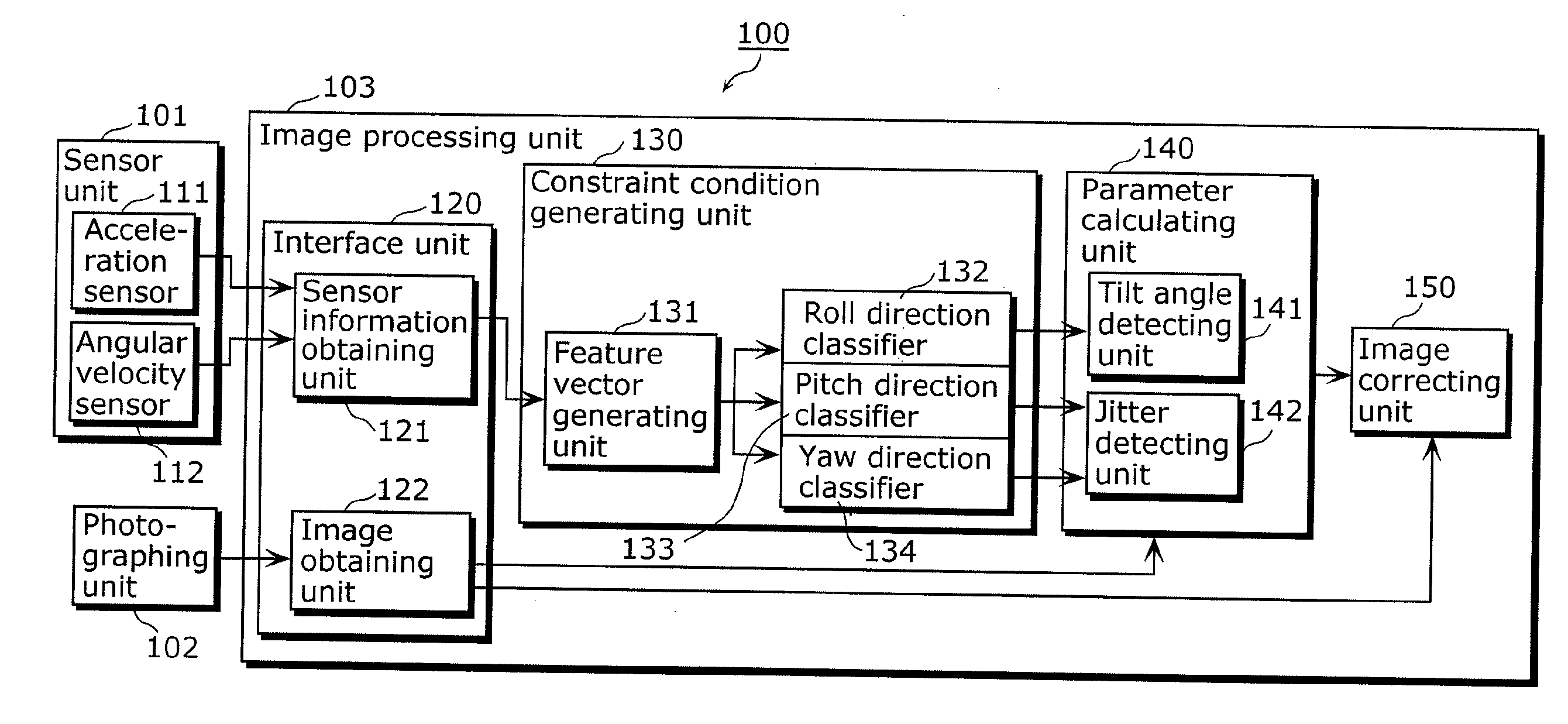
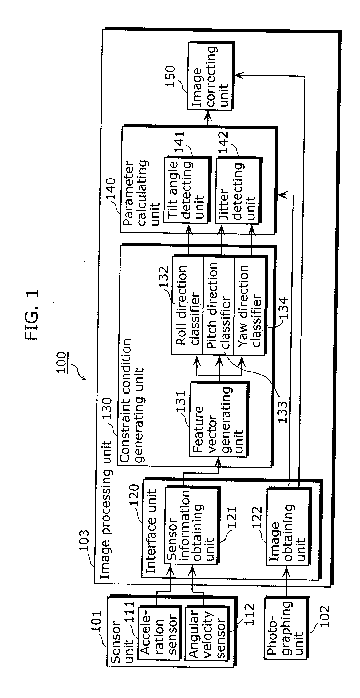
[0069]FIG. 1 is a block diagram showing a function configuration of a photographing device 100 in the first embodiment of the present invention. As shown in FIG. 1, the photographing device 100 includes a sensor unit 101, a photographing unit 102, and an image processing unit 103.
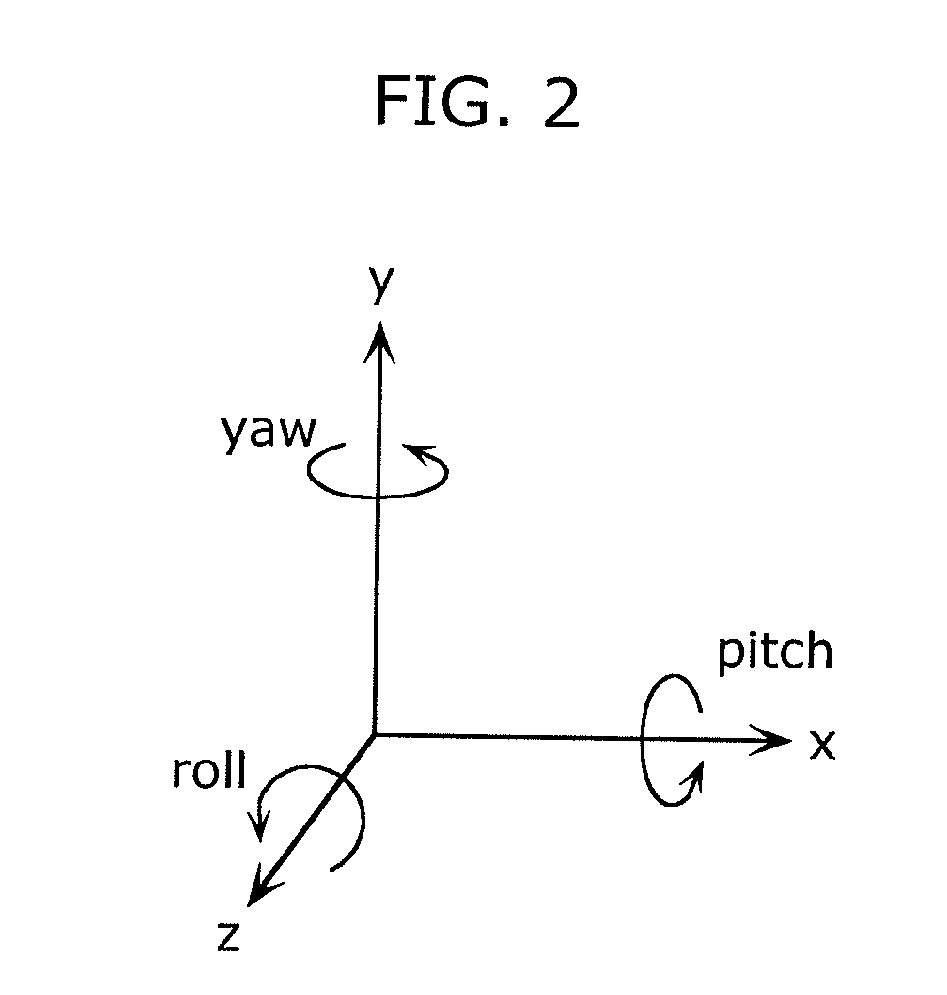
[0070]The sensor unit 101 has an acceleration sensor 111 and an angular velocity sensor 112. The sensor unit 101 measures movements of the photographing device 100, based on acceleration in three axis directions (x, y, and z axis directions) which are orthogonal to one another and based on angular velocities of rotations (roll, pitch, and yaw) around these three axes. Then, the sensor unit 101 outputs the measurement results to the image processing unit 103.
[0071]It should be noted that, for convenience of explanation, an x-y-z coordinate system is set such that an optical axis of a lens in the photographing device 100 coincides with the z axis, in the present embodiment. Regarding the angular velocities in...
second embodiment
[0132]Next, a photographing device in the second embodiment of the present invention is described.
[0133]FIG. 14 is a diagram showing a function configuration of a photographing device 1000 in the second embodiment of the present invention. The photographing device 1000 in the present embodiment is different from the photographing device 100 in the first embodiment in that the sensor unit 101 has two angular velocity sensors. Note that components which are the same as those in the first embodiment are assigned the same reference numerals as used in the first embodiment and, thus, the explanation of these components is omitted.
[0134]Each of a first angular velocity sensor 1001 and a second angular velocity sensor 1002 is an angular velocity sensor which measures angular velocities around three axes orthogonal to one another, and is a sensor which measures movements of the photographing device 1000. Here, the first angular velocity sensor 1001 and the second angular velocity sensor 100...
third embodiment
[0142]Next, a photographing device in the third embodiment of the present invention is described.
[0143]FIG. 16 is a diagram showing a function configuration of a photographing device 2000 in the third embodiment of the present invention. The photographing device 2000 is an in-vehicle photographing device in which a straight-ahead direction of an automobile coincides with an optical axis direction of the photographing device 2000. This is to say, in the case of the photographing device 2000, rotational displacements in the captured video data, namely, motion elements in the roll direction, are minute. When the motion elements are averaged through time, they can be approximated as “no change”. On account of this, it can be said that it is only parallel displacements that exist in images captured by the photographing device 2000. Thus, the photographing device 2000 in the present embodiment is different from the photographing device 100 in the first embodiment in that a roll direction ...
PUM
 Abstract
Description
Claims
Application Information
 - R&D
- Intellectual Property
- Life Sciences
- Materials
- Tech Scout
- Unparalleled Data Quality
- Higher Quality Content
- 60% Fewer Hallucinations
Browse by: Latest US Patents, China's latest patents, Technical Efficacy Thesaurus, Application Domain, Technology Topic, Popular Technical Reports.
© 2025 PatSnap. All rights reserved.Legal|Privacy policy|Modern Slavery Act Transparency Statement|Sitemap|About US| Contact US: help@patsnap.com