
Heat dissipating structure of high power LED projector lamp

a technology of led projector lamps and heat dissipation structures, which is applied in the direction of discharge tube main electrodes, semiconductor devices of light sources, light and heating apparatus, etc., can solve the problems of heat dissipation, requires extra electricity, contradict the conception, etc., and achieves the effect of effective dissipation of heat of high power, improved heat dissipation efficiency, and improved heat dissipation structur

Inactive Publication Date: 2010-09-30
CELSIA TECH TAIWAN INC
View PDF2 Cites 14 Cited by
  • Summary
  • Abstract
  • Description
  • Claims
  • Application Information

AI Technical Summary

Benefits of technology

[0007]It is a primary object of the invention to provide a heat dissipating structure of a high power LED projector lamp, which can effectively dissipate the heat of a high power LED to improve the heat dissipating efficiency without an additional fan.
[0008]Another object of the invention is to provide a heat dissipating structure of a high power LED projector lamp, which can reduce the size of the LED projector lamp.
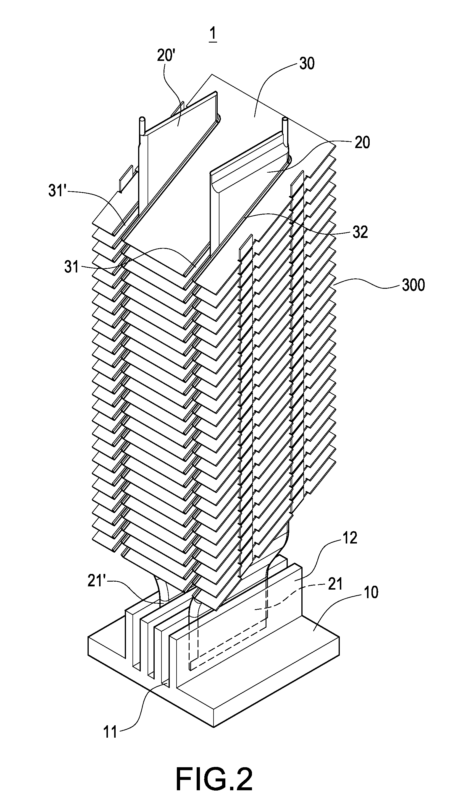
[0009]To achieve the foregoing objects, the present invention provides a heat dissipating structure of a high power LED projector lamp comprising a heat-conducting plate, a plate type heat pipe and a plurality of heat dissipating fins. One side of the heat-conducting plate is provided with a plurality of grooves for being embedded by one end of the plate type heat pipe, where those two are perpendicular to one another. Furthermore, the heat dissipating fins are stacked with an inclined angle and parallelly arranged with gaps, in which the heat dissipating fins have a plurality of slots for accommodating the plate type heat pipe. Hence, the heat generated from the high power LEDs can be conducted quickly and the heat conduction efficiency will be improved.
[0010]In comparison with the conventional LED projector lamp, the present invention can promote the heated air within the gaps to rise by disposing the slant heat dissipating fins on both sides of the plate type heat pipe. It can not only rapidly conduct the heat generated from the high power LED but also improve heat conduction efficiency of the heat dissipating fins. Moreover, the integrated exterior size and its occupying space can be reduced because the heat dissipating fins are aslant stacked at intervals. Because the heat dissipating structure of the present invention has the plate type heat pipe conducting heat rapidly and the heat dissipating fins having large heat-dissipating areas, it can dissipate the heat of high power LEDs by natural convection without consuming any electricity.

Problems solved by technology

However, high power of the LEDs brings the problem of heat dissipation.
Nevertheless, most of the LED projector lamps are provided with many heat dissipating fins, which will occupy a large space.
However, it requires consuming extra electricity when the fan is operating, which contradicts the conception of power saving and environment protecting.

Method used


Image

  • Heat dissipating structure of high power LED projector lamp
  • Heat dissipating structure of high power LED projector lamp
  • Heat dissipating structure of high power LED projector lamp

Examples


Embodiment Construction

[0017]The technical characteristics, features and advantages of the present invention will become apparent in the following detailed description of preferred embodiments with reference to the accompanied drawings, and the preferred embodiments are used for illustrating the present invention only, but not intended to limit the scope of the present invention.

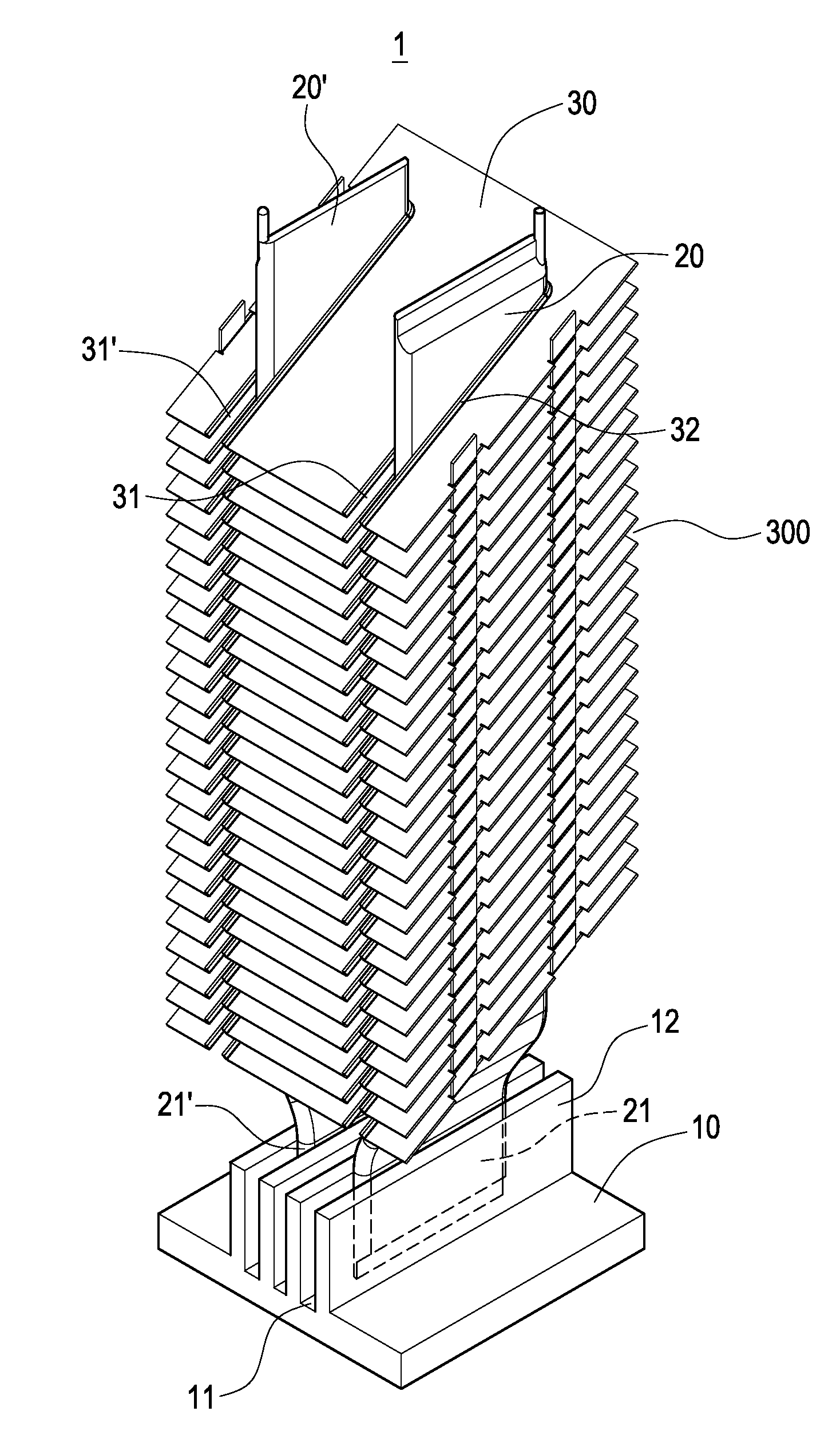
[0018]Referring to FIG. 2, the heat dissipation structure 1 comprises a heat-conducting plate 10, two plate type heat pipes 20, 20′ and a plurality of heat dissipating fins 30. The heat-conducting plate 10 is made of metal with good thermo-conductivity, such as copper or silver. One side of the heat-conducting plate 10 is provided with a plurality of grooves 11 for being embedded one end of the plate type heat pipes 20, 20′, and each of the grooves 11 is formed between two side plates 12.

[0019]The plate type heat pipes 20, 20′ are of a barlike shape. One end of each of the plate type heat pipes 20, 20′ is embedded in one of the gr...


PUM


Abstract

A heat dissipating structure is capable of dissipating heat quickly in a high power LED projector lamp to improve the heat dissipating efficiency. The structure includes a heat-conducting plate, a plate type heat pipe and a plurality of heat dissipating fins. One side of the heat-conducting plate provides a plurality of grooves for mounting one end of the plate type heat pipe, wherein those two are perpendicular to each other. Furthermore, the heat dissipating fins having a plurality of slots are stacked and arranged at intervals for disposing the plate type heat pipe with an inclined angle. Hence, the heat generated from the high power LED will be conducted quickly and the heat dissipating efficiency will be improved.

Description

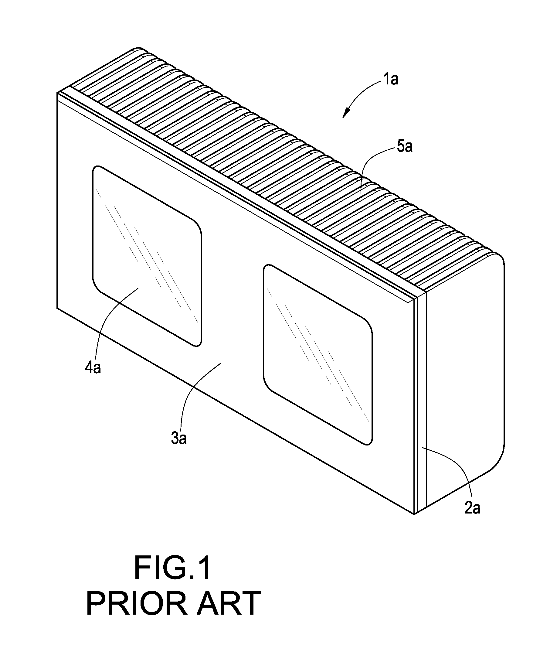
BACKGROUND OF THE INVENTION[0001]1. Field of the Invention[0002]The present invention generally relates to a heat sink, and more particularly to a heat dissipating structure disposed in a high power light emitting diode (LED) lamp.[0003]2. Description of Prior Art[0004]There are many projector lamps, which are applied as lighting devices in many places such as exhibitions, stores, etc., on the market.[0005]The technology of light emitting diodes (LEDs) grows and becomes mature because of the features of low power consumption, long service life, small size and quick response. The LED lamps gradually substitute traditional light bulbs and are extensively used in various lighting devices. However, high power of the LEDs brings the problem of heat dissipation. It needs to be considered about the heat dissipating structure of the high power LEDs applied in the projector lamps.[0006]With reference to FIG. 1, an LED projector lamp 1a has a metal housing 2a, wherein a high power LED (not sh...

Claims


Application Information

Patent Timeline
Patent Type & Authority Applications(United States)
IPC IPC(8): F28D15/00H01J7/24
CPCF21K9/00F28D15/0233F21V29/76F21V29/006F21V29/71F28F2215/12F21Y2115/10F28D15/0275F28F1/32F21V29/51
Inventor MEYER, IV, GEORGE ANTHONY.SUN, CHIEN-HUNGCHEN, CHIEH-PING
Owner CELSIA TECH TAIWAN INC
Learn More