
Ultrasonic sensor

a technology of ultrasonic sensor and detector, applied in the field of ultrasonic sensor, can solve the problems that ultrasonic sensor may erroneously detect curbstones, ultrasonic sensor, and 58091 having narrow directivity characteristic cannot satisfy an object to detect obstacles in a wide detection area

Inactive Publication Date: 2010-09-30
DENSO CORP
View PDF12 Cites 31 Cited by
  • Summary
  • Abstract
  • Description
  • Claims
  • Application Information

AI Technical Summary

Benefits of technology

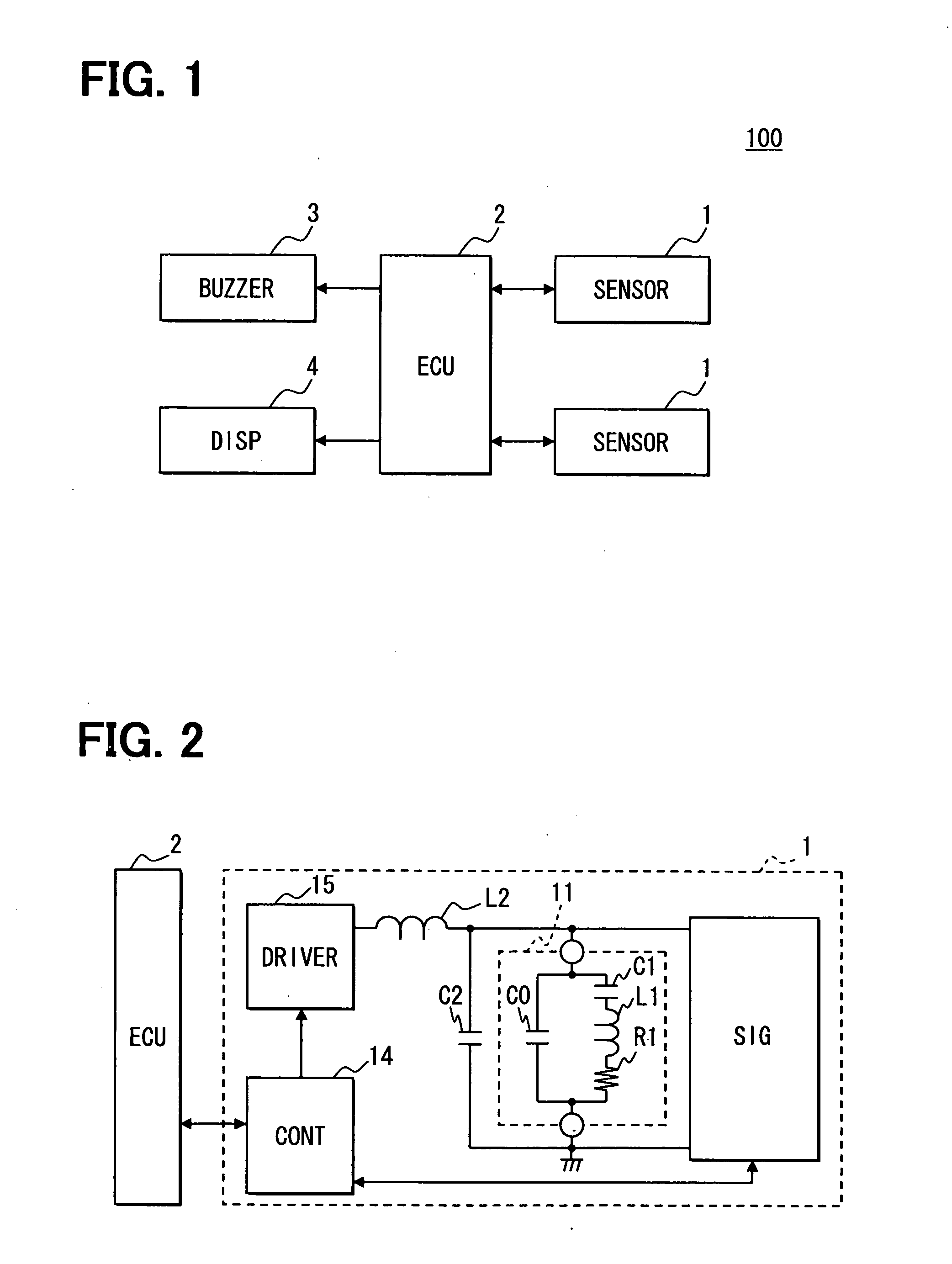
[0006]According to one aspect of the present invention, an ultrasonic sensor comprises a single element of an ultrasonic transducer including at least one combination of an equivalent series capacitor C1, an equivalent series inductor L1, and an equivalent series resistance R1. The ultrasonic transducer further includes an equivalent parallel capacitor C0. The ultrasonic sensor further comprises a drive circuit configured to drive the ultrasonic transducer. The ultrasonic sensor further comprises an inductor L2 connected in series between the ultrasonic transducer and the drive circuit. The drive circuit is configured to switch a driving frequency of the ultrasonic transducer. A first resonance frequency of the equivalent series capacitor C1 and the equivalent series inductor L1 is F0. A second resonance frequency determined by at least the equivalent parallel capacitor C0 and the inductor L2 is Fp. The drive circuit is configured to drive the ultrasonic transducer while switching the driving frequency to one of the first resonance frequency F0 and the second resonance frequency Fp.
[0007]According to another aspect of the present invention, an ultrasonic sensor comprises a single element of an ultrasonic transducer including at least one Combination of an equivalent series capacitor C1, an equivalent series inductor L1, and an equivalent series resistance R1. The ultrasonic transducer further includes an equivalent parallel capacitor C0. The ultrasonic sensor further comprises a drive circuit configured to drive the ultrasonic transducer. The ultrasonic sensor further comprises a tra...

Problems solved by technology

Therefore, an ultrasonic sensor may erroneously detect a curbstone located on a road surface in a parking area, a road surface, and / or the like as an obstacle at a distance of several meters when the directivity characteristic of an ultrasonic sensor is not limited to a narrow range.
However, the ultrasonic sensor of JP-A-2002-58091 having a narrow directivity characteristic cannot satisfy an object to detect an obstacle in a wide detection area, such as a periphery of a vehicle, rather than an obstacle at a distance of several meters away.
On the other hand, when an ultrasonic sensor has a wide directivity characteristic to detect an obstacle at a distance of several meters away, as described above, the ultrasonic sensor may erroneously detect a curbstone on a road surface in a parking area, a road surface, and / or the like as an obstacle.
Therefore, the conventional structure has a problem that multiple ultrasonic sensor elements having different directivity characteristics are required respectively for different detection areas.
However, it is difficult to obtain excellent directivity characteristics having different ranges in one ultrasonic sensor element.

Method used


Image

  • Ultrasonic sensor
  • Ultrasonic sensor
  • Ultrasonic sensor

Examples


embodiment

[0025]As follows, an embodiment will be described with reference to drawings. FIG. 1 is a block diagram showing an obstacle detecting system 100. The obstacle detecting system 100 shown in FIG. 1 is mounted to a vehicle. The obstacle detecting system 100 includes an ultrasonic sensor 1, an ECU 2, a buzzer 3, and a display device 4. The ultrasonic sensor 1, the ECU 2, the buzzer 3, and the display device 4 are connected with each other via an in-vehicle LAN, such as a controller area network (CAN), which conforms to a communications protocol. An electronic control unit (ECU) 2 is mainly configured of a microcomputer including a CPU, a ROM, a RAM, a backup RAM, and the like (none shown). The ECU 2 performs various kinds of operations by executing various kinds of control programs stored in the ROM. For example, the ECU 2 executes an operation related to transmission of a burst wave from the ultrasonic sensor 1 and reception of a reflective wave from an obstacle. The ECU 2 detects a di...


PUM


Abstract

A single element of an ultrasonic transducer includes at least one combination of an equivalent series capacitor C1, an equivalent series inductor L1, and an equivalent series resistance R1. The ultrasonic transducer further includes an equivalent parallel capacitor C0. An inductor L2 is connected in series between the ultrasonic transducer and the drive circuit. A first resonance frequency of the equivalent series capacitor C1 and the equivalent series inductor L1 is F0. A second resonance frequency determined by at least the equivalent parallel capacitor C0 and the inductor L2 is Fp. A drive circuit drives the ultrasonic transducer while switching the driving frequency of the ultrasonic transducer to one of the resonance frequency F0 and the resonance frequency Fp.

Description

CROSS REFERENCE TO RELATED APPLICATIONS[0001]This application is based on and incorporates herein by reference Japanese Patent Application No. 2009-84314 filed on Mar. 31, 2009.FIELD OF THE INVENTION[0002]The present invention relates to an ultrasonic sensor.BACKGROUND OF THE INVENTION[0003]Conventionally, an ultrasonic sensor, which is for detecting the distance from an object or existence of an object by transmitting an ultrasonic wave at a predetermined frequency and receiving a reflective wave reflected from an object, is known. In recent years, an ultrasonic sensor is used to detect an obstacle around a vehicle. A directivity characteristic of an ultrasonic sensor radially diffuses. Therefore, an ultrasonic sensor may erroneously detect a curbstone located on a road surface in a parking area, a road surface, and / or the like as an obstacle at a distance of several meters when the directivity characteristic of an ultrasonic sensor is not limited to a narrow range. For example, JP...

Claims


Application Information

Patent Timeline
IPC IPC(8): G01S15/04H01L41/09G01S15/931
CPCB06B1/0284B06B2201/70G01S2015/938G01S7/524G01S15/931G01S7/52003
Inventor TERAZAWA, HIDEHITO
Owner DENSO CORP
Learn More