
Nano-material catalyst device

a catalyst device and nanomaterial technology, applied in the field of catalysts for electrochemical reactions, can solve the problems of high cost of platinum, achieve the effect of reducing the cost of such catalyst devices, and reducing the cost of fuel cell systems, etc., and achieving the same effective total surface energy

Inactive Publication Date: 2010-09-16
BRICOLEUR PARTNERS LP
View PDF1 Cites 7 Cited by
  • Summary
  • Abstract
  • Description
  • Claims
  • Application Information

AI Technical Summary

Benefits of technology

[0013]An aspect of at least one of the embodiments disclosed herein includes the realization that a catalyst device providing about the same performance of a platinum catalyst device can be manufactured with other less expensive materials by using nano-scale reactive metal particles of such less expensive materials. In modern solid polymer membrane fuel cells, platinum is the primary ingredient in the catalyst devices because platinum has a high surface energy density. However, platinum is costly. Thus, the cost of such catalyst devices, and thus fuel cell systems, as well as other systems using platinum catalysts, can be reduced by using other less expensive materials that are configured to provide about the same effective total surface energy as modern platinum catalyst devices.
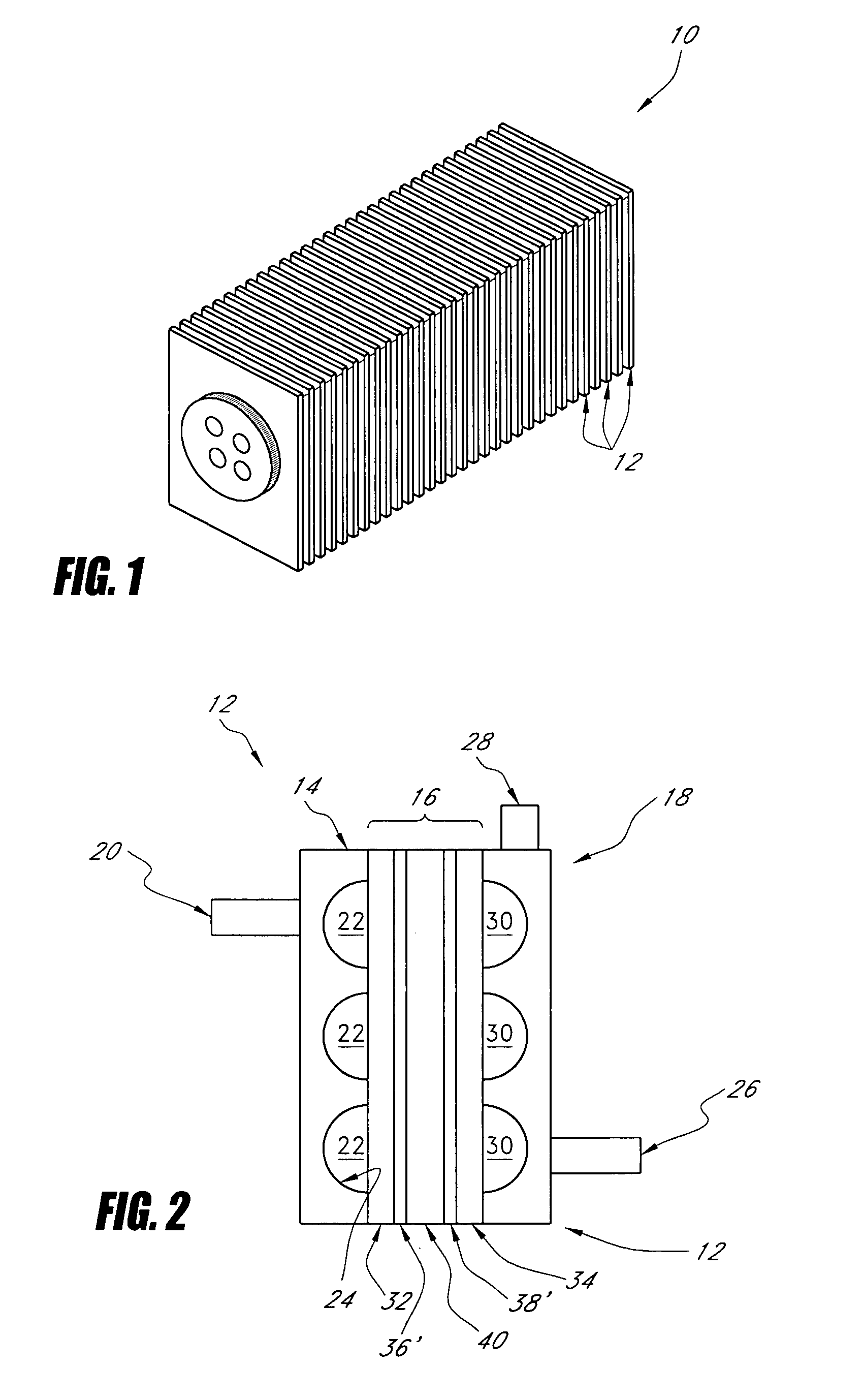
[0021]In other embodiments, it is preferable that the reactive metal particles and metal substrate particles be compressed and sintered by heating such that a 3-dimensional compact is formed. Preferably, the compact has a fraction of its surface area within the inside volume of the compact, and most preferably, a significant portion of the active area lies within the interior volume, with the remaining internal area comprising void volume. To increase the active area and allow for effective gas and fluid flow, nanoparticles are blended with larger, metal, substrate particles. The larger, metal, substrate particles provide, amongst other value, structural integrity, and the outer surface of the metal substrate particles are coated with nanoparticles for increased reactive surface area.
[0023]In some embodiments, the composition is volumetrically compressed relative to its original volume such that the composition maintains mechanical stability and also provides sufficient permeability to the reacting species.

Problems solved by technology

However, platinum is costly.

Method used


Image

  • Nano-material catalyst device
  • Nano-material catalyst device
  • Nano-material catalyst device

Examples


example 1

Preparation of an Electrode

[0108]About 0.15 grams of nickel powder (15 nm) and 1.35 grams of micron-nickel powder (0.5 micron) were blended in a vial. The resulting mixture was poured into a ¾″ die containing a ¾″ circle of expanded nickel metal. The die was then volumetrically compressed to 1500 psi and held at this pressure for 30 seconds. The resulting electrode was removed from the die and placed in a furnace at 500° C. for 1 hour.

example 2

Electrode Performance

[0109]Cathodes were tested using a half-cell apparatus to independently test the electrode activity for hydrogen and oxygen generation. Electrolyte was a 33% KOH solution against a zinc-wire reference electrode. FIG. 8 shows a set of voltammograms for oxygen generation and a set for hydrogen generation. The most inefficient electrodes, shown as lines 300 are the lowest and highest lines on the hydrogen and oxygen curves, respectively. Electrodes made completely of micron-sized nickel also perform poor, shown on lines 302. However, with the addition of metal nanoparticles into the mixture, performance increases dramatically. Lines 304-307 illustrate this enhanced performance.

[0110]Referring to FIGS. 18 and 19, a comparison is shown between the efficiency and electrical performance of the described electrodes versus typical electrodes. Efficiency is defined as the amount of energy required to make hydrogen versus the energy inherent to the molecule. FIG. 18 shows ...


PUM

PropertyMeasurementUnit
diameteraaaaaaaaaa
diameteraaaaaaaaaa
diameteraaaaaaaaaa

Abstract

A catalyst member comprising a blended mixture of nano-scale metal particles compressed with larger metal particles and sintered to form a structurally stable member of any desired shape. The catalyst member can be used in one of many different applications; for example, as an electrode in a fuel cell or in an electrolysis device to generate hydrogen and oxygen.

Description

CROSS-REFERENCE TO RELATED APPLICATIONS[0001]This application is a continuation-in-part of U.S. patent application Ser. No. 10 / 983,933, filed Nov. 8, 2004, the contents of which are incorporated herein by reference.BACKGROUND OF THE INVENTION[0002]1. Technical Field[0003]The inventions disclosed herein generally relate to catalysts for electrochemical reactions, for example, electrodes for use in fuel cells and electrolysis devices.[0004]2. Related Art[0005]Hydrogen is a renewable fuel that produces zero emissions when used in a fuel cell. In 2005, the Department of Energy (DoE) developed a new hydrogen cost goal and methodology, namely to achieve $2.00-3.00 / gasoline gallon equivalent (gge, delivered, untaxed, by 2015), independent of the pathway used to produce and deliver hydrogen. The principal method to produce hydrogen is by stream reformation. Nearly 50% of the hydrogen currently being produced is made by steam reformation, where natural gas is reacted on metallic catalyst at ...

Claims


Application Information

Patent Timeline
Patent Type & Authority Applications(United States)
IPC IPC(8): H01M8/10H01M4/02H01M4/64H01M4/90H01M4/36C25B11/06C25B9/08C25B9/19
CPCB82Y30/00H01M4/8878H01M4/8885Y02E60/522H01M4/928H01M8/1004Y02E60/523H01M4/90Y02E60/50
Inventor CARPENTER, R. DOUGLASDOPP, ROBERT BRIANMCGRATH, KIMBERLY
Owner BRICOLEUR PARTNERS LP
Learn More