
Method to condense and recover carbon dioxide from fuel cells

Active Publication Date: 2010-08-26
1304338 ALBERTA
View PDF3 Cites 35 Cited by
  • Summary
  • Abstract
  • Description
  • Claims
  • Application Information

AI Technical Summary

Problems solved by technology

The gases emitted from combustion applications can also be recovered but the economies of scale are not as attractive as a fuel cell due to a much lower concentration of carbon dioxide in the emissions stream.

Method used


Image

  • Method to condense and recover carbon dioxide from fuel cells
  • Method to condense and recover carbon dioxide from fuel cells
  • Method to condense and recover carbon dioxide from fuel cells

Examples


Embodiment Construction

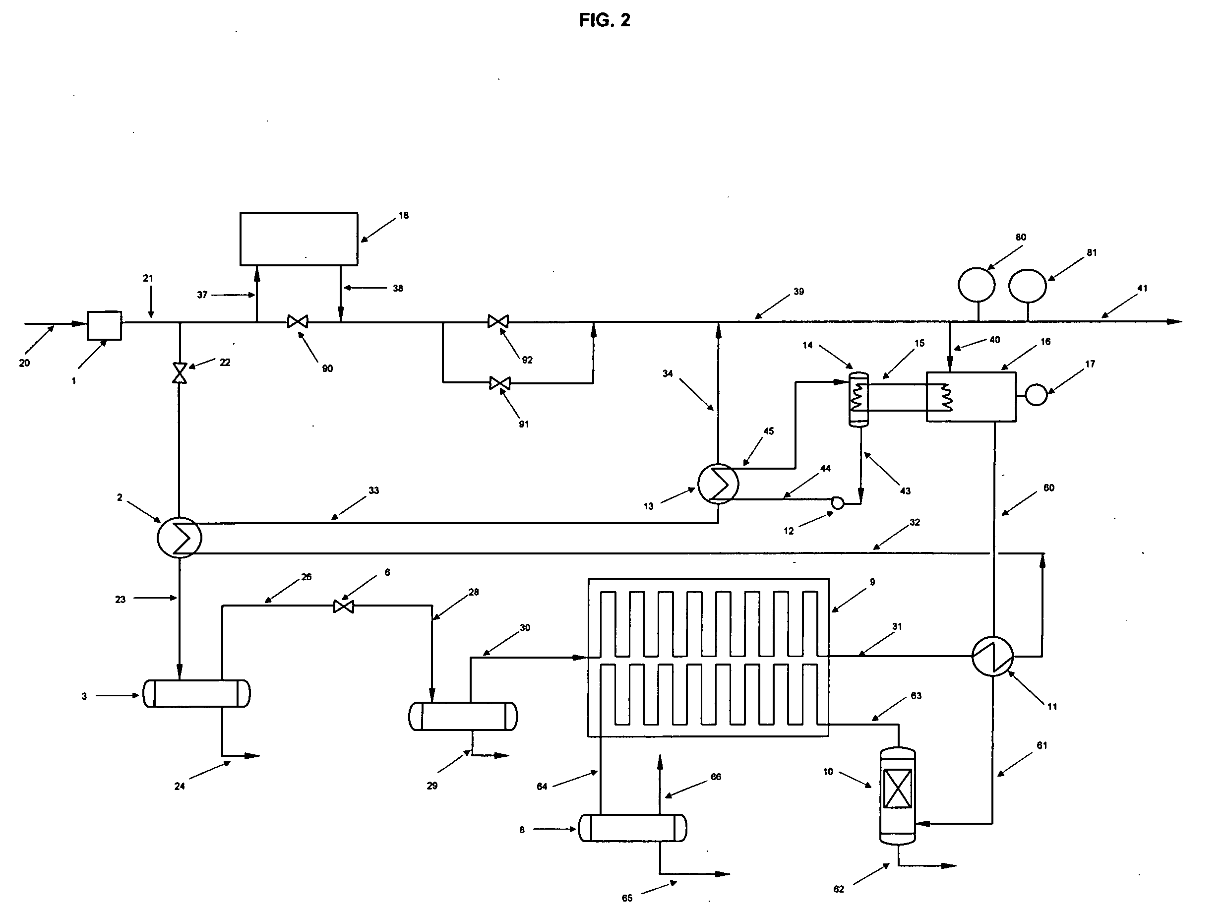
[0007]The preferred method to recover and condense carbon dioxide embodiment will now be described with reference to FIG. 1.

[0008]In this process cryogenic energy generated at gas Metering and Pressure Reduction Stations (MPRS) is recovered to condense carbon dioxide. The generation of cryogenic temperatures at MPRS is an efficient method to conserve and recover energy versus the current practice of consuming more energy (pre-heating the gas) to condense and recover carbon dioxide as a liquid and or as a solid for consumption as a commodity.

[0009]The present practice has a natural gas stream 20 entering a filter vessel 1. The filtered stream 21 is then routed through stream 37 to an hot water heat exchanger 18 for pre-heating to prevent the formation of hydrates downstream of pressure valves 91 and 92, the heat addition is controlled by temperature transmitter 80. The pre-heated gas stream 38 is then depressurized through a pressure control valves 91 and 92, this pressure reduction ...


PUM


Abstract

A method to condense and recover carbon dioxide. A first step involve providing at more than one heat exchanger, with each heat exchanger having a first flow path for passage of a first fluid and a second flow path for passage of a second fluid. A second step involves passing a stream of very cold natural gas sequentially along the first flow path of each heat exchanger until it is heated for distribution and concurrently passing a gaseous stream rich in carbon dioxide sequentially along the second flow path of each heat exchanger, allowing a gaseous portion of the gaseous stream rich in carbon dioxide to pass to a next sequential heat exchanger and capturing in a collection vessel the condensed carbon dioxide. This processes results in a cryogenic heat exchange in which natural gas at Metering and Pressure ReductionStations is first cooled by reducing its pressure through a gas expander or a pressure reducing valve and then heated in a series of stages and the gaseous stream rich in carbon dioxide stream is separated in a series of stages through sequential cryogenic carbon dioxide separation and recovery.

Description

FIELD OF THE INVENTION[0001]The present invention relates to a method of recovering carbon dioxide emitted from a fuel cell at gas Metering and Pressure Reduction Stations.BACKGROUND OF THE INVENTION[0002]In gas Metering and Pressure Reduction Stations, the gas is pre-heated before the pressure is dropped to prevent the formation of hydrates which can cause damage to the pipeline and associated equipment. The typical pressure reduction varies between 400 to 900 PSIG (pounds per square inch gage) for main transmission gas lines to local distribution lines and from 50 to 95 PSIG from local distribution lines to consumers. When gas is depressurised the temperature drops. The rule of thumb is that for every 100 pounds of pressure drop across a valve the gas temperature will drop by 7 F. When the same pressure is dropped across a gas expander the temperature drop is three times greater (21 F per 100 pounds pressure) because work is done, typically the shaft from the gas expander is conne...

Claims


Application Information

Patent Timeline
IPC IPC(8): C01B31/20C01B32/50H01M8/0668
CPCB01D53/002B01D2257/504B01D2258/0208F25J1/0027F25J1/0221F25J1/0229Y02E60/50F25J2210/60F25J2210/70F25J2220/82F25J2270/14H01M8/0668F25J1/0232
Inventor LOURENCO, JOSEMILLAR, MACKENZIE
Owner 1304338 ALBERTA
Learn More