
Automatic frequency calibration apparatus and method for a phase-locked loop based frequency synthesizer

Active Publication Date: 2010-08-26
KWANGWOON UNIV IND ACADEMIC COLLABORATION FOUND
View PDF10 Cites 37 Cited by
  • Summary
  • Abstract
  • Description
  • Claims
  • Application Information

AI Technical Summary

Benefits of technology

[0033]Example embodiments of the present invention provide an automatic frequency calibration apparatus and a method thereof for a phase-locked loop based frequency synthesizer to reduce the frequency calibration time dramatically while obtaining the frequency resolution smaller than the reference frequency.
[0038]In addition, the automatic frequency calibration apparatus generates multiple phase signals so as to convert the frequency of the VCO signal into the first digital value and then counts individually each multi-phase signal, and thus the frequency calibration speed may be enhanced.
[0039]Furthermore, the automatic frequency calibration apparatus uses the second digital value, which is a constant value, corresponding to the target frequency for the comparison, and so the frequency calibration speed in a frequency synthesizer may be enhanced.
[0040]Moreover, the automatic frequency calibration apparatus calibrates the frequency of the VCO signal with the frequency resolution smaller than the reference frequency fREF, and thus the frequency of the VCO signal may be accurately calibrated.

Problems solved by technology

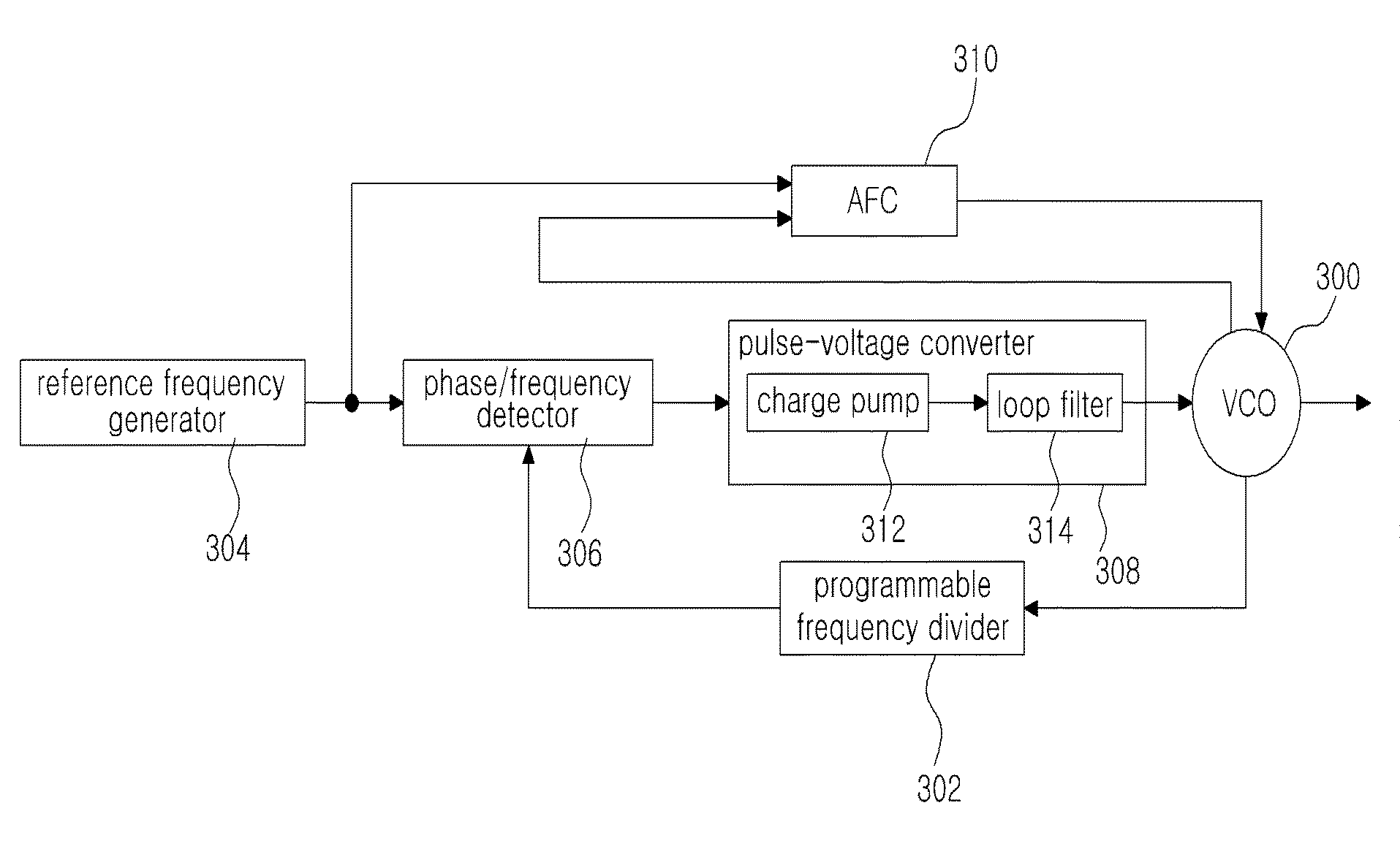
However, in the frequency synthesizer using the conventional AFC in FIG. 1, the frequency resolution of the AFC is usually limited to the reference frequency fREF, or an extremely long frequency calibration time is needed for obtaining the frequency resolution smaller than the reference frequency fREF.
On the other hand, a further important issue for the AFC is a frequency comparison method used for the frequency calibration.
However, the fundamental problem is that the frequency resolution is fixed at the reference frequency fREF due to its own voltage comparison method, and thus this calibration technique cannot be applied to the fractional-N frequency synthesizer that typically requires a frequency resolution better than the reference frequency fREF.

Method used


Image

  • Automatic frequency calibration apparatus and method for a phase-locked loop based frequency synthesizer
  • Automatic frequency calibration apparatus and method for a phase-locked loop based frequency synthesizer
  • Automatic frequency calibration apparatus and method for a phase-locked loop based frequency synthesizer

Examples


Embodiment Construction

[0054]Example embodiments of the present invention are disclosed herein. However, specific structural and functional details disclosed herein are merely representative for the purpose of describing example embodiments of the present invention, however, example embodiments of the present invention may be embodied in many alternate forms and should not be construed as limited to example embodiments of the present invention set forth herein.

[0055]Accordingly, while the invention is susceptible to various modifications and alternative forms, specific embodiments thereof are shown by way of example in the drawings and will herein be described in detail. It should be understood, however, that there is no intent to limit the invention to the particular forms disclosed, but on the contrary, the invention is to cover all modifications, equivalents, and alternatives falling within the spirit and scope of the invention. Like numbers refer to like elements throughout the description of the figu...


PUM


Abstract

An automatic frequency calibration apparatus and a method thereof for a phase-locked loop based frequency synthesizer are disclosed. The apparatus includes a frequency-to-digital converter configured to convert a frequency of a VCO output signal to a first digital value, a target value setting section configured to provide a second digital value corresponding to a target frequency, and a finite state machine configured to calibrate the frequency of the VCO output signal by using the difference of the first digital value and the second digital value. Accordingly, the calibration speed and a frequency resolution of the automatic frequency calibration apparatus in a frequency synthesizer may be enhanced.

Description

CROSS-REFERENCE TO RELATED APPLICATIONS[0001]This application claims priority from Korean Patent Application No. 2009-15264 filed on Feb. 24, 2009, the contents of which are incorporated herein by reference in its entirety.[0002]1. Technical Field[0003]Examples embodiments of the present invention relate to an automatic frequency calibration apparatus and a method thereof for a phase-locked loop based frequency synthesizer, more particularly relate to an apparatus and a method of enhancing a frequency calibration speed and resolution.[0004]2. Related Art[0005]A RF frequency synthesizer generates a local oscillation signal, and is an essential circuit element for wireless communication transmitters and receivers.[0006]The RF frequency synthesizer widely uses a phase-locked loop (PLL) technique for locking its output frequency to a target frequency.[0007]In the PLL, the time taken to lock the voltage controlled oscillator (VCO) frequency to the target frequency is referred to as a loc...

Claims


Application Information

Patent Timeline
IPC IPC(8): H03B21/00H03L7/06
CPCH03L7/087H03L7/1976H03L7/10H03L7/099H03L7/104H03L7/093
Inventor SHIN, HYUNCHOLSHIN, JAEWOOK
Owner KWANGWOON UNIV IND ACADEMIC COLLABORATION FOUND
Learn More