
Laser scanning device and calibration method thereof

a laser scanning and laser technology, applied in the field of laser scanning devices and calibration methods, can solve the problems of reducing the precision of touch sensing, taking considerable time and effort to slowly fine-tune the frequency, etc., and achieve the effect of increasing the convenience of use and fast adjusting speed

Inactive Publication Date: 2015-04-02
CORETRONIC
View PDF8 Cites 1 Cited by
  • Summary
  • Abstract
  • Description
  • Claims
  • Application Information

AI Technical Summary

Benefits of technology

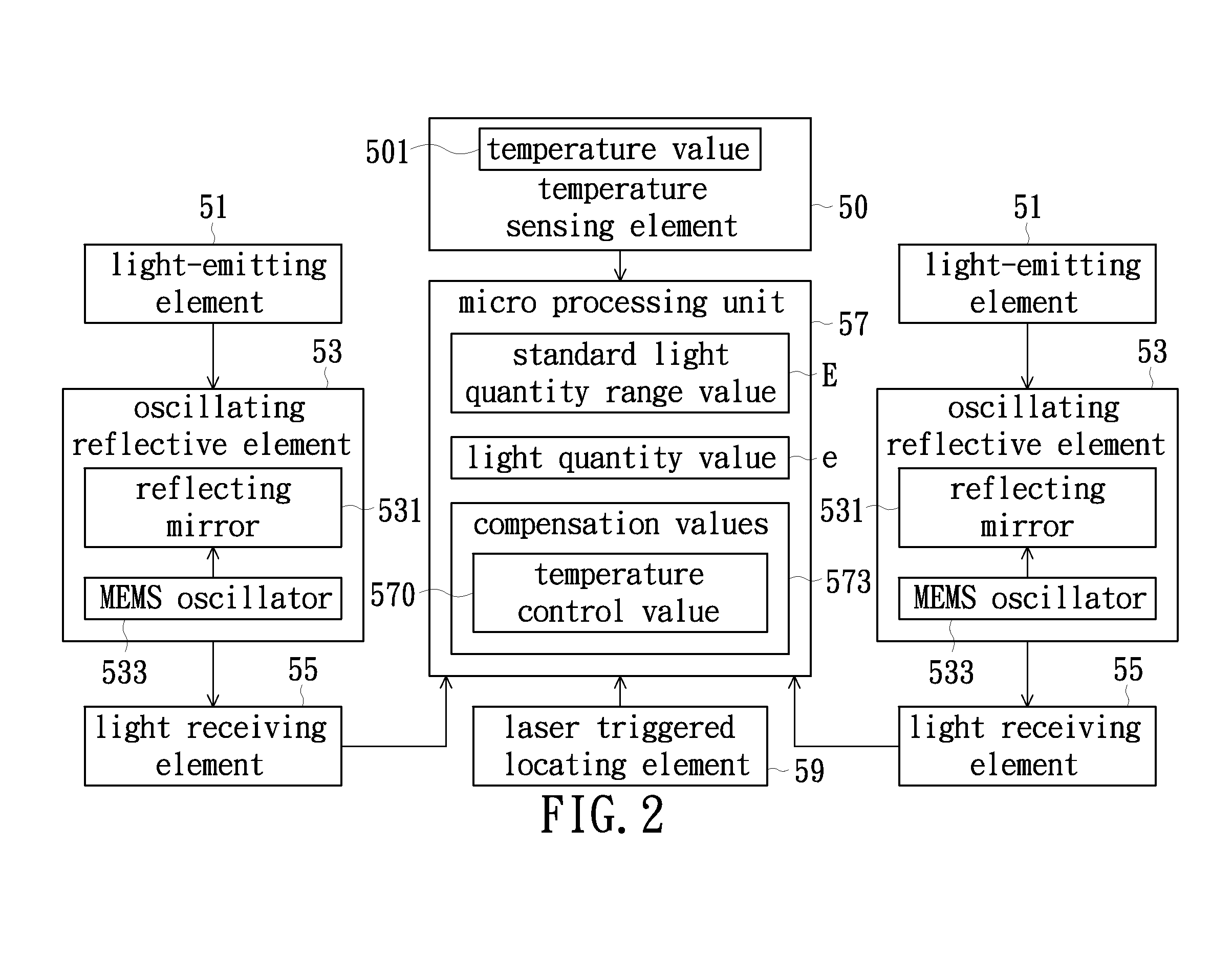
This patent discusses a calibration method for a laser scanning device that can quickly and easily adjust the swing frequency and oscillation frequency of the device when the environment temperature changes. This allows the device to quickly and accurately calibrate itself without the need for slow and gradual adjustments. The calibration method increases the speed and convenience of using the laser scanning device and ensures that it operates within the specific range of the environment temperature.

Problems solved by technology

This causes a decrease in the precision of touch sensing.
As a result, if the conventional adjusting method is used, it would take considerable time and effort to slowly fine-tune the frequency, determine the received laser light quantity by the optical receiver, and then repeat the adjusting processes.

Method used


Image

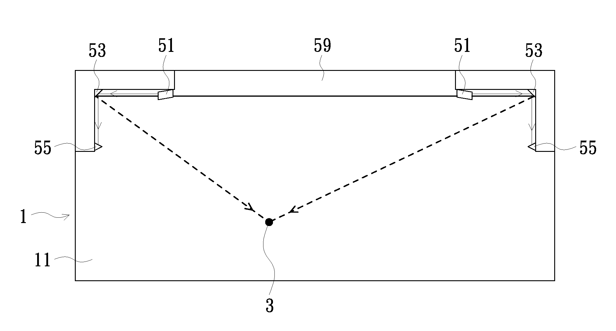
  • Laser scanning device and calibration method thereof
  • Laser scanning device and calibration method thereof
  • Laser scanning device and calibration method thereof

Examples


Embodiment Construction

[0036]In the following detailed description of the preferred embodiments, reference is made to the accompanying drawings which form a part hereof, and in which are shown by way of illustration specific embodiments in which the invention may be practiced. In this regard, directional terminology, such as “top,”“bottom,”“front,”“back,” etc., is used with reference to the orientation of the Figure(s) being described. The components of the invention may be positioned in a number of different orientations. As such, the directional terminology is used for purposes of illustration and is in no way limiting. On the other hand, the drawings are only schematic and the sizes of components may be exaggerated for clarity. It is to be understood that other embodiments may be utilized and structural changes may be made without departing from the scope of the invention. Also, it is to be understood that the phraseology and terminology used herein are for the purpose of description and should not be ...


PUM


Abstract

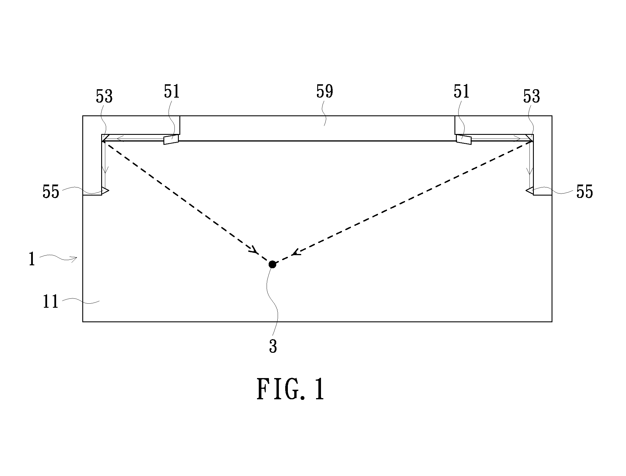
A laser scanning device and a calibration method thereof are provided. The laser scanning device includes a light-emitting element, an oscillating reflective element, a light receiving element and a micro processing unit. The oscillating reflective element is configured to swing back and forth in an adjustable oscillation frequency, such that laser beams emitted from the light-emitting element are reflected to a predetermined scan region. When a swing angle of the oscillating reflective element is affected by a change of the environment temperature, an oscillation frequency of the laser scanning device is directly changed corresponding to the current environment temperature by the micro processing unit such that the oscillating reflective element correctly swings in a predetermined angle range.

Description

FIELD OF THE INVENTION[0001]The invention relates to a laser scanning device and a calibration method thereof, and more particularly to a laser scanning device capable of calibrating a laser swing angle according to the current environment temperature.BACKGROUND OF THE INVENTION[0002]As the touch technology continuously progresses, when the position touch sensing is to be performed on a wide plane, not only the pressure sensitive type touch screen but also the surface scanning type optical touch system can be applied so as to determine the corresponding coordinate of the touch point on the plane as a basis of image interactions.[0003]A conventional surface scanning type optical touch system includes a laser transmitter, an oscillating reflective element, a sensor and an optical receiver. The oscillating reflective element is, for example, an oscillating reflective mirror controlled by a voltage. The oscillating reflective element is configured to swing back and forth in a predetermi...

Claims


Application Information

Patent Timeline
IPC IPC(8): G02B26/10
CPCG02B26/105
Inventor CHEN, YUNG-CHIHHSU, HUNG-CHUN
Owner CORETRONIC
Learn More