
Coated article supporting photocatalytic layer and UV-reflecting underlayer, and/or method of making the same

Active Publication Date: 2010-08-19
GUARDIAN GLASS LLC
View PDF9 Cites 3 Cited by
  • Summary
  • Abstract
  • Description
  • Claims
  • Application Information

AI Technical Summary

Benefits of technology

[0004]The mechanism of photoinduced hydrophilicity, or photocatalytic splitting of water, is based on photogenerated electrons and holes. Electrons are generated in the conduction band, and holes are generated in the valence band. The mechanism can be generally modeled by the following:TiO2+hv→e−+h+ (surface on TiO2)Electron reaction: e−+O2→O2+− (super oxide radical)2O2+−+2H2O→2*OH−+O2Surface reaction: h++OH−→*OHTitanium dioxide is a good photocatalyzer in terms of reactivity, durability, safety, absorption of UV light, and scratch resistance.
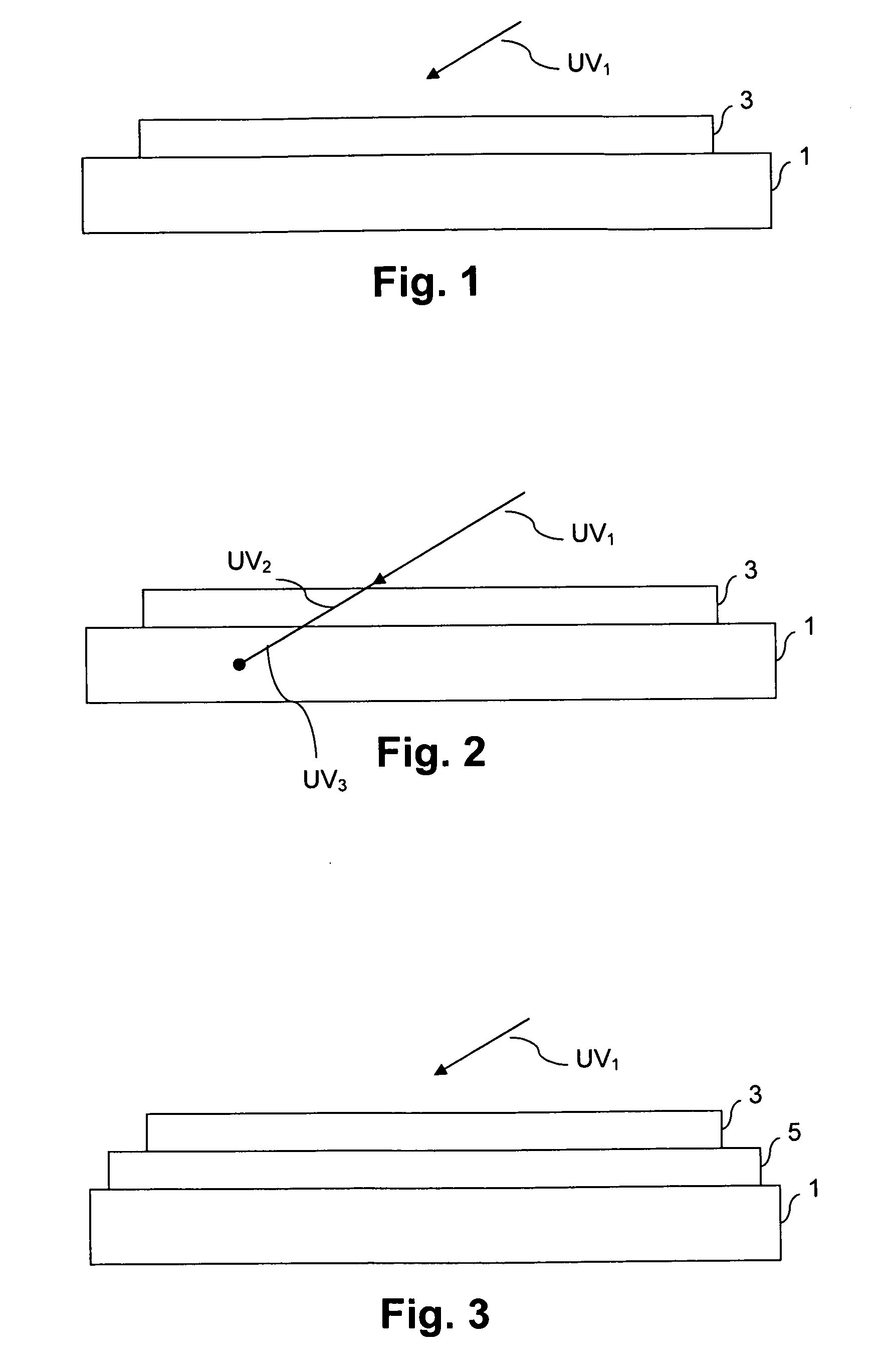
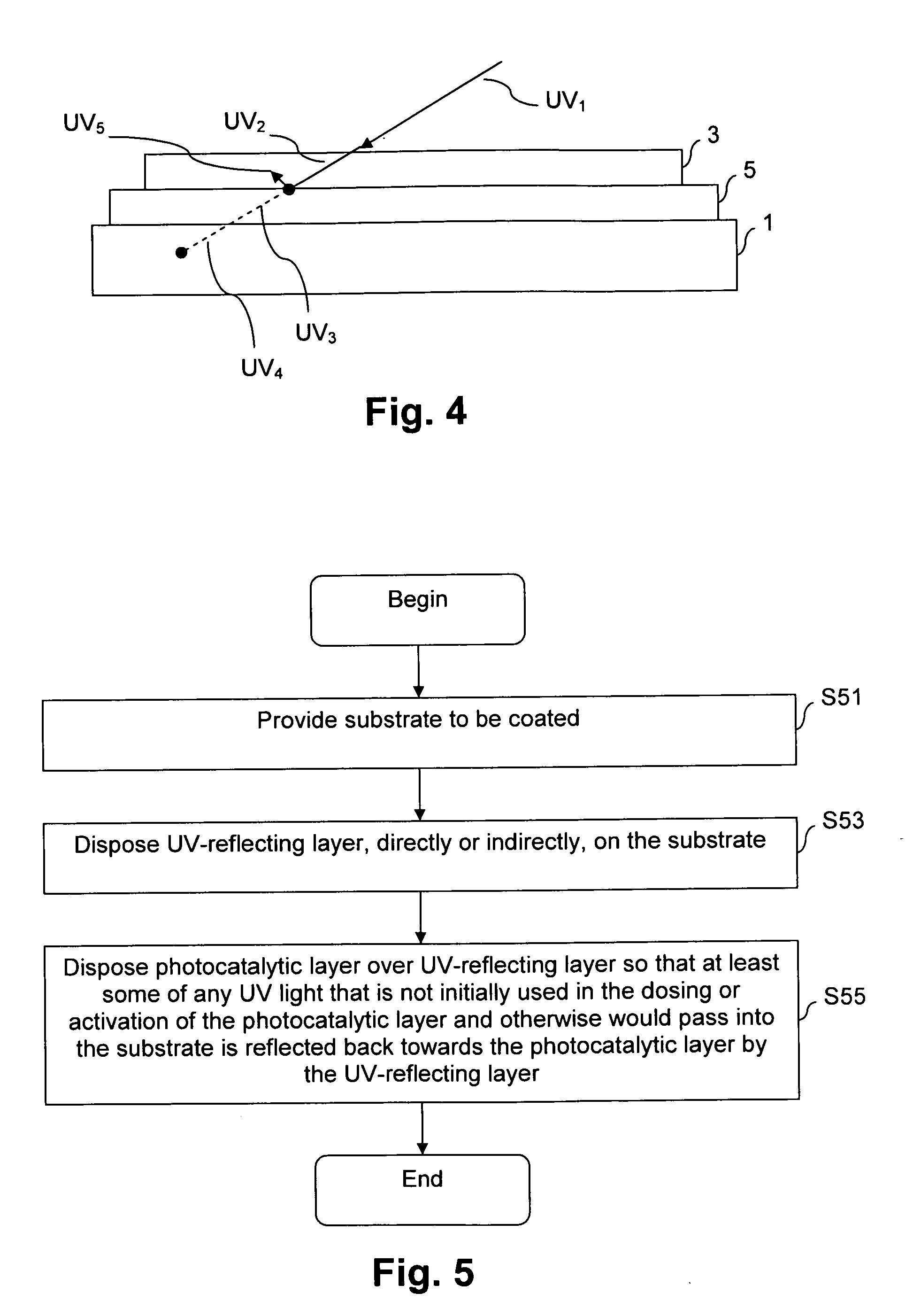
[0007]The inventors of the instant application have discovered a way of significantly reducing the dosing time to enable quick activation of photocatalysts. More particularly, the inventors of the instant application have surprisingly and unexpectedly discovered that providing a UV-reflecting underlayer results in superior reductions to the dosing time to enable quick activation of photocatalysts.

Problems solved by technology

One disadvantage associated with these types of semiconductors, and specifically titanium dioxide, is that given its band gap, UV light is necessary for the desired performance properties.

Method used


Image

  • Coated article supporting photocatalytic layer and UV-reflecting underlayer, and/or method of making the same
  • Coated article supporting photocatalytic layer and UV-reflecting underlayer, and/or method of making the same
  • Coated article supporting photocatalytic layer and UV-reflecting underlayer, and/or method of making the same

Examples


example 1

[0026]As noted above, the UV-reflecting underlayer may be a single or monolithic layer. Accordingly, in this example, the bottom UV-reflecting coating may comprise at least 0.1% by weight aluminum oxide (e.g., Al2O3 or other suitable stoichiometry), and at least 0.1% by weight material having a higher refractive index than the aluminum oxide so that as large a portion of the UV light as possible is reflected and as large a portion of visible light as possible can be emitted. One suitable coating of this sort is described in U.S. Pat. No. 6,906,463, the entire contents of which is hereby incorporated herein by reference. The higher index materials may include, for example, zirconium oxide, yttrium oxide, hafnium oxide, oxides of rare earth metals, etc.

example 2

[0027]As noted above, the UV-reflecting underlayer may be a multilayer structure. Accordingly, in this example, the UV-reflecting coating may comprise a multilayer stack based on materials having matching or substantially matching refractive indexes. For example, U.S. Pat. Nos. 7,169,441 and 5,449,413 disclose various examples of acceptable multilayer coatings that reflect most solar radiations having wavelengths shorter than 350 nm. The entire contents of both U.S. Pat. Nos. 7,169,441 and 5,449,413 are hereby incorporated herein by reference.

[0028]Advantageously, using the techniques of certain example embodiments enables the lifetime of the photocatalytic coating to be extended. It is also noted that the glass substrate may be heat treated in certain example embodiments so that the glass substrate is either heat strengthened (e.g., at a temperature of at least about 200 degrees C., more preferably at least about 250 degrees C.) or thermally tempered (e.g., at a temperature of at l...


PUM

PropertyMeasurementUnit
Fractionaaaaaaaaaa
Percent by massaaaaaaaaaa
Energyaaaaaaaaaa

Abstract

Certain example embodiments relate to articles supporting photocatalytic layers that also include UV-reflecting underlayers, and / or methods of making the same. In certain example embodiments, the inclusion of a UV-reflecting underlayer surprisingly and unexpectedly results in the reduction of dosing time to enable quick activation of the photocatalytic coating. For example, dosing time may be reduced from a few hours to a few minutes or even seconds in certain example embodiments. The UV-reflecting underlayer may be a single-layer coating or a multi-layer stack.

Description

FIELD OF THE INVENTION[0001]Certain example embodiments of this invention relate to coated articles supporting photocatalytic layers, and / or methods of making the same. More particularly, certain example embodiments of this invention relate to articles supporting photocatalytic layers that also include UV-reflecting underlayers, and / or methods of making the same. In certain example embodiments, the inclusion of a UV-reflecting underlayer surprisingly and unexpectedly results in the reduction of dosing time to enable quick activation of the photocatalytic coating.BACKGROUND AND SUMMARY OF EXAMPLE EMBODIMENTS OF THE INVENTION[0002]Semiconductor catalysis, given its oxidative and superhydrophilic nature, is known. Indeed, this technique has attracted a great deal of attention because of the wide range of potential applications for removing toxic organic an inorganic species from coated articles such as, for example, automobile windshields, house windows, building and shower doors, tabl...

Claims


Application Information

Patent Timeline
IPC IPC(8): B32B9/04B05D3/00
CPCC03C2217/71C03C17/3417
Inventor SHARMA, PRAMOD K.MELLOTT, NATHAN P.
Owner GUARDIAN GLASS LLC
Learn More