[0007]It is an object of the invention to provide an improved layout modification engine for fixing layout entities in the
integrated circuit design in which the
processing time of the improved layout modification engine is reduced.
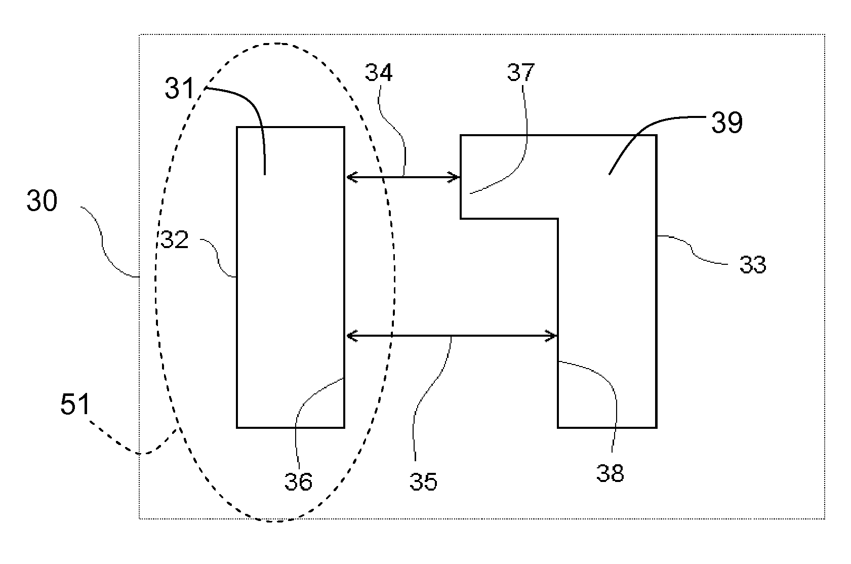
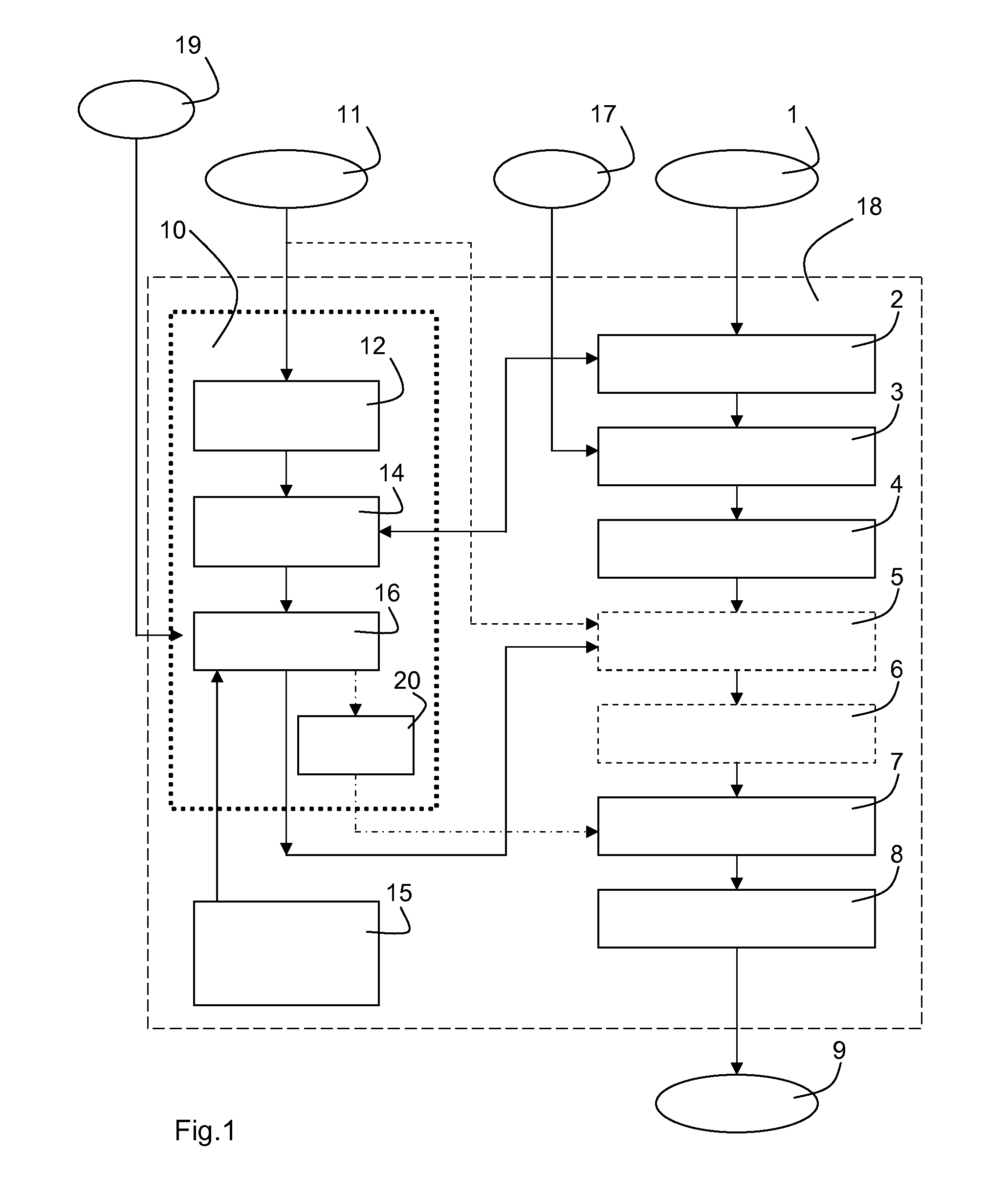
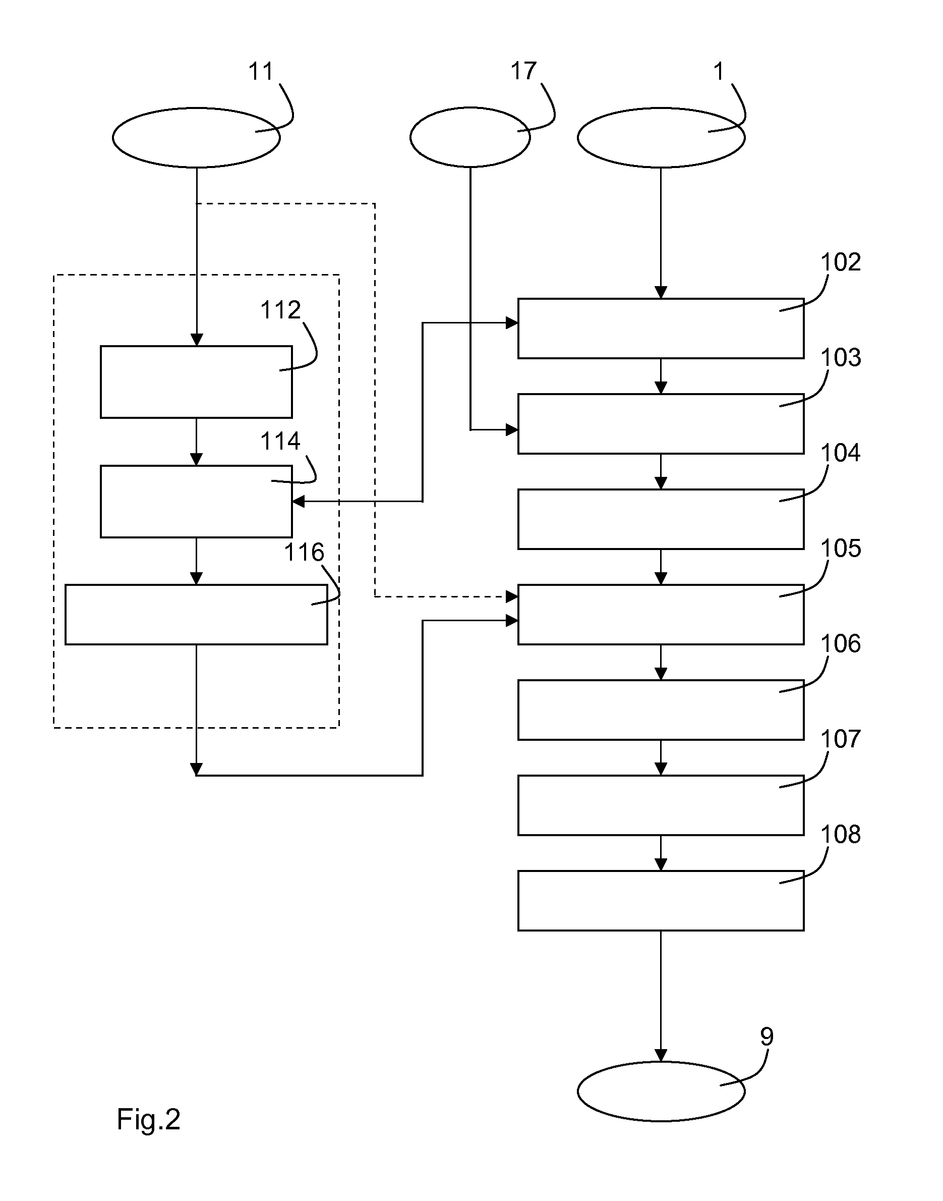
[0010]The layout modification engine according to the invention actively forces the conflicting situations to be resolved before the layout modification engine solves the set of constraints to generate instructions for adapting the circuit layout. The conflict-solver converts the fixed layout entity into the set of fixed layout elements which is subsequently entered into the set of constraints. Because the layout modification engine converts the fixed layout entity into the set of fixed layout elements, the modifying step of the layout modification engine for modifying the circuit layout to comply with the set of constraints will encounter less conflict situations which will reduce the
processing time of the layout modification engine.
[0011]In the known layout modification engines the set of constraints are solved while fixing the fixed layout entity to their restrained position. Adding the additional requirement that a specific layout entity must be restrained to a certain position may result in a conflict. In these known layout modification engines, these conflicts only arise during the solving of the set of constraints and during the
adaptation of the circuit layout to comply with the set of constraints. This may cause the layout modification engine to fail to provide a solution to the set of constraints or may cause the layout modification engine to require an excessive amount of calculating time and power to generate a solution to the set of constraints. In the layout modification engine according to the invention, the circuit layout is analyzed to detect conflicts between the fixed layout element and the free layout elements. Actively resolving possible conflicts by converting the fixed layout entity into the set of fixed layout elements prevents that the conflict causes the layout modification engine to try to find a solution where there is no solution due to the conflict or where the solution is excessively complex due to the conflict. By providing the set of fixed layout elements to the layout modification engine, the occurrence of conflicts is reduced and the processing time of the layout modification engine required to generate a solution to the set of constraints is reduced.
[0015]In an embodiment of the layout modification engine, the conflict-solver is rule-based. A benefit of this embodiment is that the rule-based conflict-solver solves the detected conflicts in a reproducible and predictable manner. Furthermore, the use of a rule-based conflict-solver minimizes manual inputs which further reduces the processing time of the layout modification engine by reducing
idle time waiting for the manual inputs. The known layout modification engines typically
signal conflicts during the solving of the set of constraints or provide a listing of the conflicts after the solving of the set of constraints. A user of the
system has to manually inspect the (
list of) conflicts and has to manually solve each individual conflict which is relatively
time consuming. Furthermore, substantially identical conflicts may be solved by a user in a different manner which results in un-predictable differences within the integrated circuit. Using the rule-based conflict-solver for converting the fixed layout entities into the set of fixed layout elements reduces the manual inputs and solves the conflicts in a reproducible manner.
[0020]In an embodiment of the layout modification engine, the
receiver is arranged for receiving the fixed layout entity and / or for receiving the free layout entities via: a listing of fixed and / or free layout entities, and / or a selected area, all layout entities within the selected area being fixed layout entities or all layout entities outside the selected area are fixed layout entities, and / or a
label of a sub-circuit within the circuit layout, all layout entities within the sub-circuit or a selection of the layout entities of the sub-circuit being fixed layout entities or free layout entities. A benefit of this embodiment is that it allows a flexible input of the fixed layout entities into the conflict-solver of the layout modification engine according to the invention. For example, a user may identify a selected area within a circuit layout, for example, by indicating a rectangle, a circle, an
ellipse, a polygon or any combination of any of these selected areas in a computer representation of the integrated circuit. The
receiver, for example, receives the selected area and identifies all layout entities within the selected area as fixed layout entities.
Integrated circuit layouts also often comprise sub-circuits which are repeated at several locations within the
integrated circuit layout. The
receiver is arranged for receiving the
label of the sub-circuit for receiving the fixed layout entities. The receiver may, for example, identify all layout entities within the sub-circuit as fixed layout entities or may only identify a selection of the layout entities within the sub-circuit as fixed layout entities. This embodiment enables the layout modification engine according to the invention to solve a conflict within the sub-circuit only once and re-apply the solution to the conflict every time the sub-circuit is placed within the circuit layout.
[0022]In an embodiment of the layout modification engine, the constraint adapter is arranged for fixing the position of the adapted set of fixed layout elements via converting variables representing a layout element in the set of constraints into constant values representing the predefined position assigned to the fixed layout element, or by adding an additional constraint for restraining the fixed layout element or by converting variables representing a layout element in the set of constraints into a further variable defining a virtual reference point of a particular layout entity together with a relative position within the particular layout entity of the fixed layout elements for generating a relatively
fixed position. The virtual reference point of the particular layout entity may be, for example, a local origin of a sub-circuit or a
cell or may be, for example, a center of gravity of the sub-circuit or cell or may be any other arbitrary point of the sub-circuit or cell. A benefit when converting the variables in the set of constraints into the constant values being the predefined position assigned to the fixed layout element is that it reduces the number of variables in the set of constraints which generally simplifies the solving of the set of constraints, generally reducing the processing time of the layout modification engine. A benefit when adding an additional constraint to the set of constraints is that the set of constraints does not need to be scanned thoroughly to identify the variables associated with the fixed layout element. This additional scanning generally requires processing time of the constraint adapter increasing the total processing time of the layout modification engine. Just adding an additional constraint in which the variable is set to the predefined position prevents the need for an additional scan through the set of constraints and thus simplifies the constraint adapter.


