Eureka AIR delivers breakthrough ideas for toughest innovation challenges, trusted by R&D personnel around the world.

Log transport system

Active Publication Date: 2010-08-12
TIMBER AUTOMATION LLC
View PDF5 Cites 13 Cited by
  • Summary
  • Abstract
  • Description
  • Claims
  • Application Information

AI Technical Summary

Benefits of technology

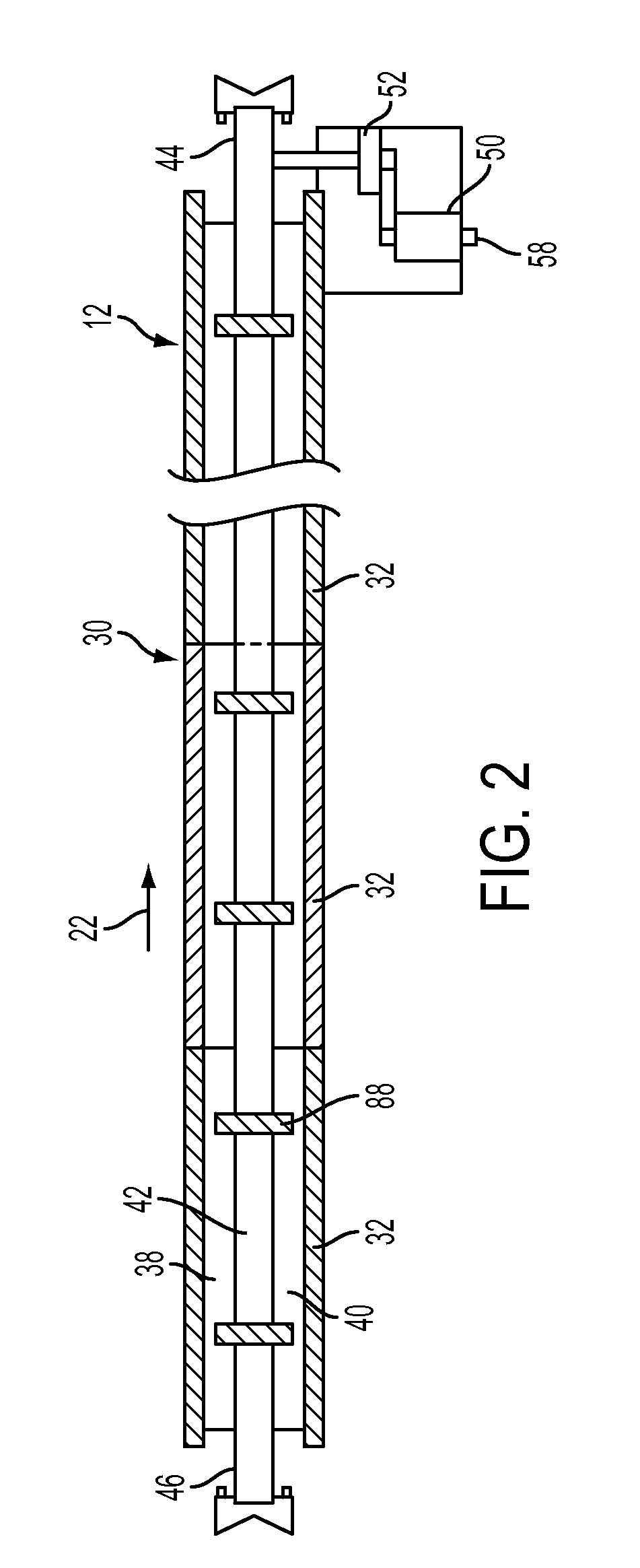
[0011]According to an embodiment, the present invention provides a system for transporting a log, including first and second parallel tracks that extend longitudinally. Each of the tracks can be formed of track portions, or sections, arranged collinearly to define first and second track surfaces respectively. At least one of the tracks preferably has a nonlinear cross section. The tracks are supported by a frame so that the first track portions are substantially collinear and the first track surface is uniform and continuous in the longitudinal direction of the track to reduce transverse motion of the log during transport.

Problems solved by technology

Each log is typically non-uniform along its length, i.e., the log varies in cross-sectional size or shape or defines curves or other non-uniformities.
As a result, the chain and chain drive mechanisms may not support the logs evenly, and the logs may therefore move relative to the mechanism in a rocking, bouncing, or sliding motion.
Additionally, conventional systems can introduce a certain amount of unwanted motion while transporting the logs, for example, if the track sections are not uniform or not aligned correctly or if the drive mechanism does not move at a uniform speed.
The unwanted motion of the logs can adversely affect the accuracy of the scanning or other processing, resulting in sub-optimal processing of the logs.
If the chains are driven by a single motor, the uneven stretching and wearing can increase the stress on the chains and cross members and decrease the performance of the system.
If the chains are driven by separate drive mechanisms, the uneven wearing and stretching of the chains can result in different speeds of the chains, thus imparting additional, nonlinear motion to the logs, adversely affecting other processes such as scanning.
Undesirably, however, the holders may not prevent the logs from sliding in a direction parallel to the chain, for example, while the chain is being started or stopped.
Also, even if the holders move at a constant speed, nonuniformities in the track can cause unwanted motion, as described above.
However, these belts have problems with difficulty in tracking the belts used for log transport, the logs move on the belts or the belts move under the log, and the entire circumference of the logs cannot be scanned.
Chain link systems require lubrication, are heavy, noisy, prone to undesirable chordal action, and have a maximum safe speed of 400 feet per minute.
While some advertised chain speeds are above 500 feet per minute, this speed is not practical, cannot be safely maintained using chains, and reduces the life of the chain.

Method used


Image

  • Log transport system
  • Log transport system
  • Log transport system

Examples


Embodiment Construction

[0027]The present inventions now will be described more fully hereinafter with reference to the accompanying non-limiting drawings. Indeed, these inventions may be embodied in many different forms and should not be construed as limited to the embodiments set forth herein; rather, these embodiments are provided so that this disclosure will satisfy applicable legal requirements. Like numbers refer to like elements throughout.

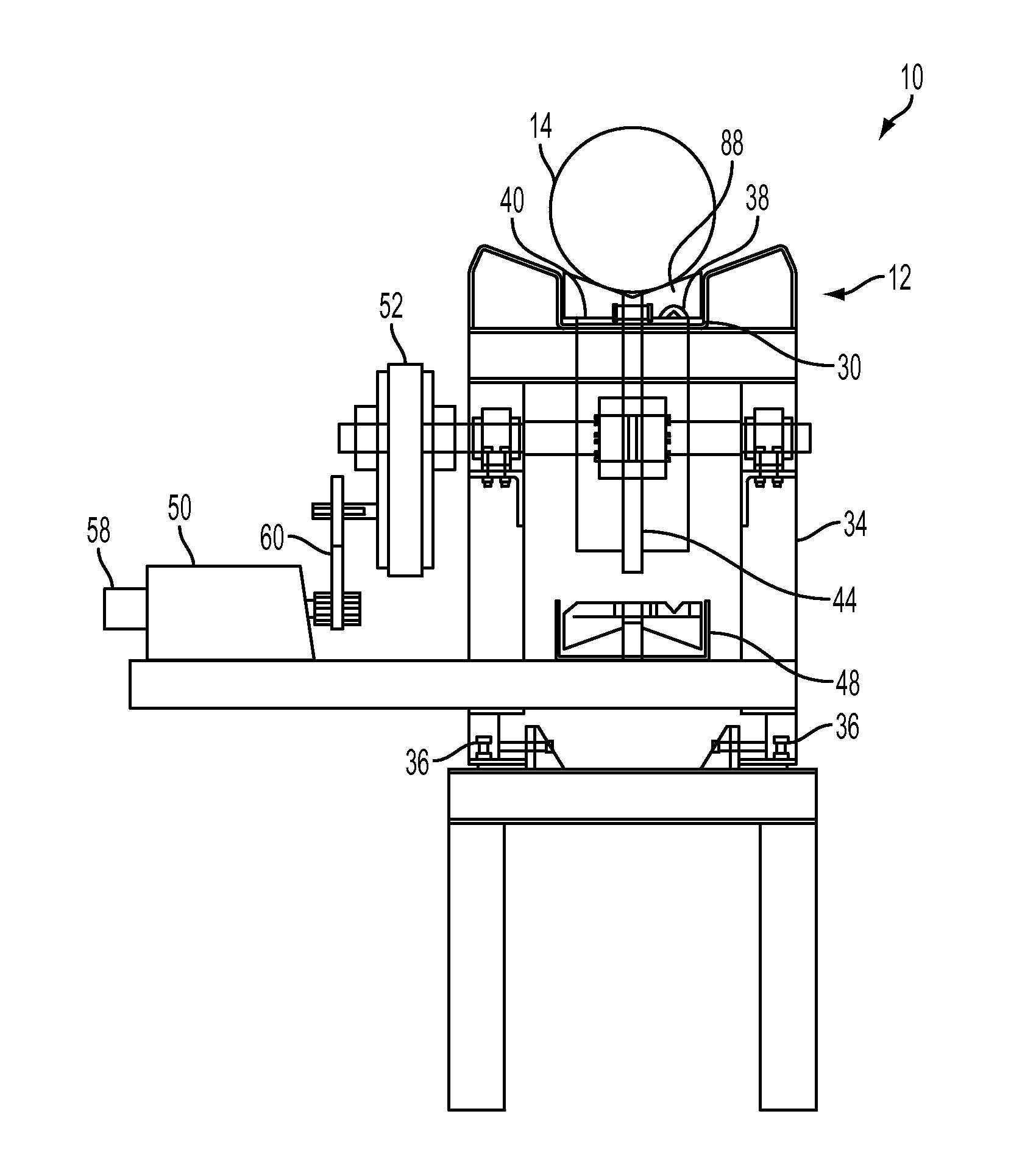
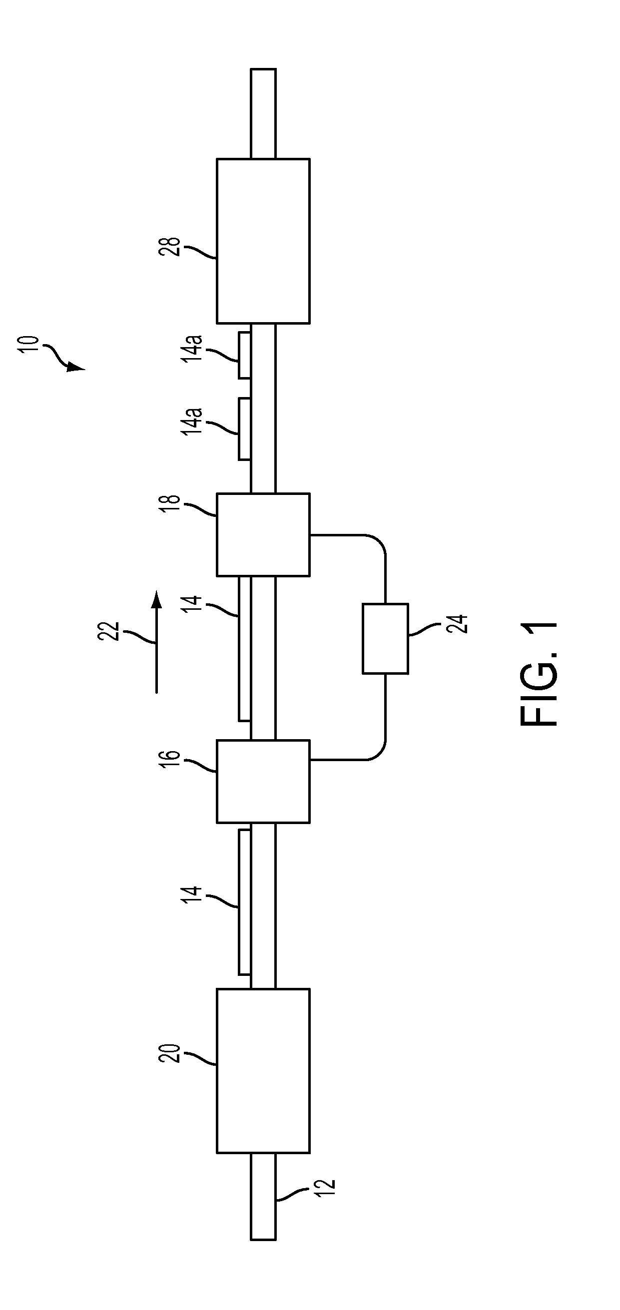
[0028]Referring now to the figures and, in particular, to FIG. 1, there is illustrated a log transport system 10 according to one embodiment of the present invention. The log transport 10 system includes a conveyor 12 for transporting the logs 14 through or past one or more processing devices, such as a computerized scanning device 16 and / or a cutting device 18. For example, logs can be loaded endo from a preceding conveyor or from the side using loading device 20 can first load the logs 14 onto the conveyor 12. The loader 20 can load the logs 14 individually in a...


PUM


Abstract

A system for lineally transporting logs, lugs therefore, and an associated method are provided. The system includes first and second tracks connected to a frame to provide continuous track surfaces. Lugs having support surfaces that correspond to the track surfaces are configured to be driven longitudinally along the tracks by a continuous conveyor belt.

Description

[0001]This application claims priority to U.S. Provisional Patent Application Ser. No. 61 / 151,933, filed 12 Feb. 2009, the complete disclosure of which is incorporated herein by reference.FIELD OF INVENTIONS[0002]The present invention relates to log transport systems and, more particularly, relates to a system and method for transporting logs in a direction of motion while preventing appreciable unwanted motion, such as in directions transverse to the direction of motion, to thereby facilitate processing of the logs, such as by scanning, cutting, and the like.DESCRIPTION OF RELATED ART[0003]During the processing of tree logs, long sections of logs are often transported for a variety of processing steps. For example, according to one conventional process, tree length logs, or “stems,” are transported lineally on a motor-driven chain or chain drive mechanism supported by tracks formed of track sections that are welded or bolted together. The logs are passed by or through a scanning de...

Claims


Application Information

Patent Timeline
IPC IPC(8): B27B1/00B65G15/44B65G19/22
CPCB27B31/006B65G2201/0282B65G17/10B65G17/065
Inventor KRAUSS, JIMKRAUSS, JOSH
Owner TIMBER AUTOMATION LLC
Why Eureka
Eureka Blog
Learn More