[0005]A challenging
voltage regulation application, and an important application for the present invention, is reactor switching at high voltage and extra high voltage transmission levels. In these applications, current reignitions across the arc gap in the circuit interrupter cause very steep voltage increases in the reactor between turns. This electrical stress caused by reignition during reactor switching is similar to that caused by
lightning only that it occurs much more frequently. That is, reactor switching typically occurs on a daily basis, whereas
lightning typically occurs much less frequently, such as a yearly basis in general. The
daily operation and frequent reignitions during reactor switching cause cumulative damage to reactors that reduce the life of these expensive devices. Frequent reignitions can also cause damage to the interrupter by
puncturing the
nozzle materials, usually Teflon®, which in turn increases the likelihood of further reignitions. Also, the strong pressure developed in interrupters can force the current to zero prematurely, which further increases the voltage on the reactor thus requiring the interrupter to withstand even higher voltages. It is therefore important to switch the reactors in a manner that minimizes damages caused to the reactors, the interrupters, and other electric system components, from reignitions occurring during the switching process.
[0006]Switching of capacitor banks is also a common occurrence in electric power systems. The inductive
reactance of motors in home and industrial use cause less than unity power factors, which if uncorrected can increase system losses and cause voltage levels delivered to end-use customers to drop to unacceptable levels.
Capacitor banks are usually switched into the electric
power circuits during high levels of inductive loading, typically during the
daylight and early
evening hours when most people are awake and using electric power, to correct the
power factor, reduce delivery losses, and boost the voltage to the end-use customers. Once the high level inductive loading subside, typically at night, the capacitor banks are switched out of the electric power circuit. Daily cyclical use of capacitors is therefore a common practice to balance the capacitive
reactance with inductive loads, and thus minimizing the stated problem, as electric loads increase and decrease on a daily basis.
[0009]A need therefore exists for circuit interrupters for reactor, capacitor, load and
line switching at distribution and transmission voltages up to high voltage and extra high voltage levels that that minimizes damages caused to electric system components from flash-over across the interrupter arc gap during the switching process. In particular, because reactors used for
voltage regulation are operated relatively frequently and at
high transmission voltages, it is important to switch the reactors in a manner that minimizes damages caused to the reactors and the circuit interrupters from flash-over during the switching process. There is, therefore, a continuing need for a circuit interrupter suitable for switching reactors on high voltage and extra
high voltage transmission lines to extend the life of the reactors and the reactor switching circuit interrupters by minimizing the frequency of high voltage flash-over that can causes damage and life reduction.SUMMARY OF THE INVENTION
[0010]The present invention meets the needs described above in a limited flash-over electric power switch suitable for reactor, capacitor, load and
line switching at distribution and transmission voltages up to high voltage and extra high voltage levels that that minimizes damages caused to electric system components from flash-over during the switching process. The limited flash-over electric power switch includes a circuit interrupter that is designed to serve as a
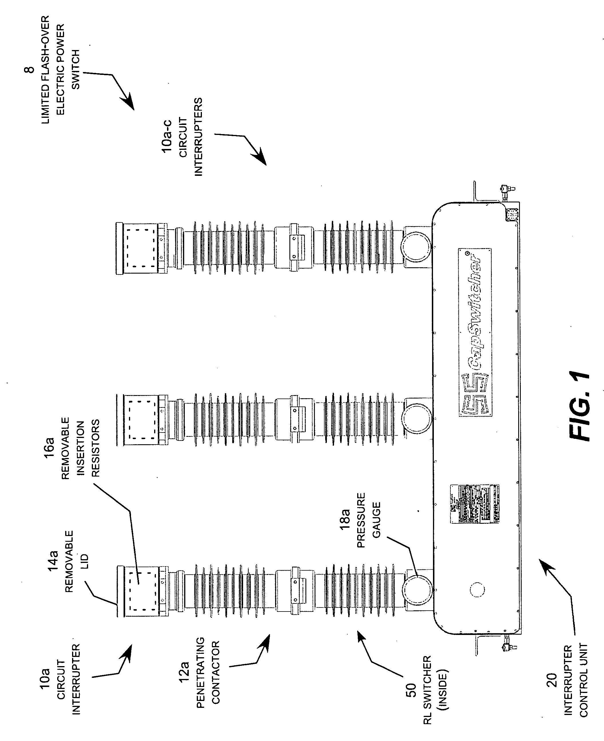
reactive load switcher (“RL switcher”) for connecting reactors into and out of high voltage and extra high voltage transmission circuits to extend the life of the reactors and reactor switching circuit interrupters by minimizing the frequency of high magnitude flash-over that can causes damage and life reduction. Although the limited flash-over electric power switch is well suited for reactor switching at high voltage and extra high voltage transmission levels, it can also be used for capacitor, load and
line switching at any desired electric power voltage level.
[0011]The limited flash-over electric power switch uses a
dielectric gas regulator and a flash-over arrestor to greatly diminish the occurrences of high voltage flash-over during operation of the circuit interrupter. The dielectric gas regulator prevents the flow of the dielectric gas into the arc gap during an initial portion of the opening
stroke of the interrupter contacts. Once the arc gap is sufficiently wide to greatly diminish the likelihood of a high voltage flash-over, the dielectric gas regulator allows the dielectric gas to flow into the arc gap to extinguish the arc. The flash-over arrestor snubs out incipient flash-over that may occur as the arc attempts to reform across the arc gap. The flash-over arrestor may be a conductive ring located on the interior surface of the nozzle in the region of the orifice.
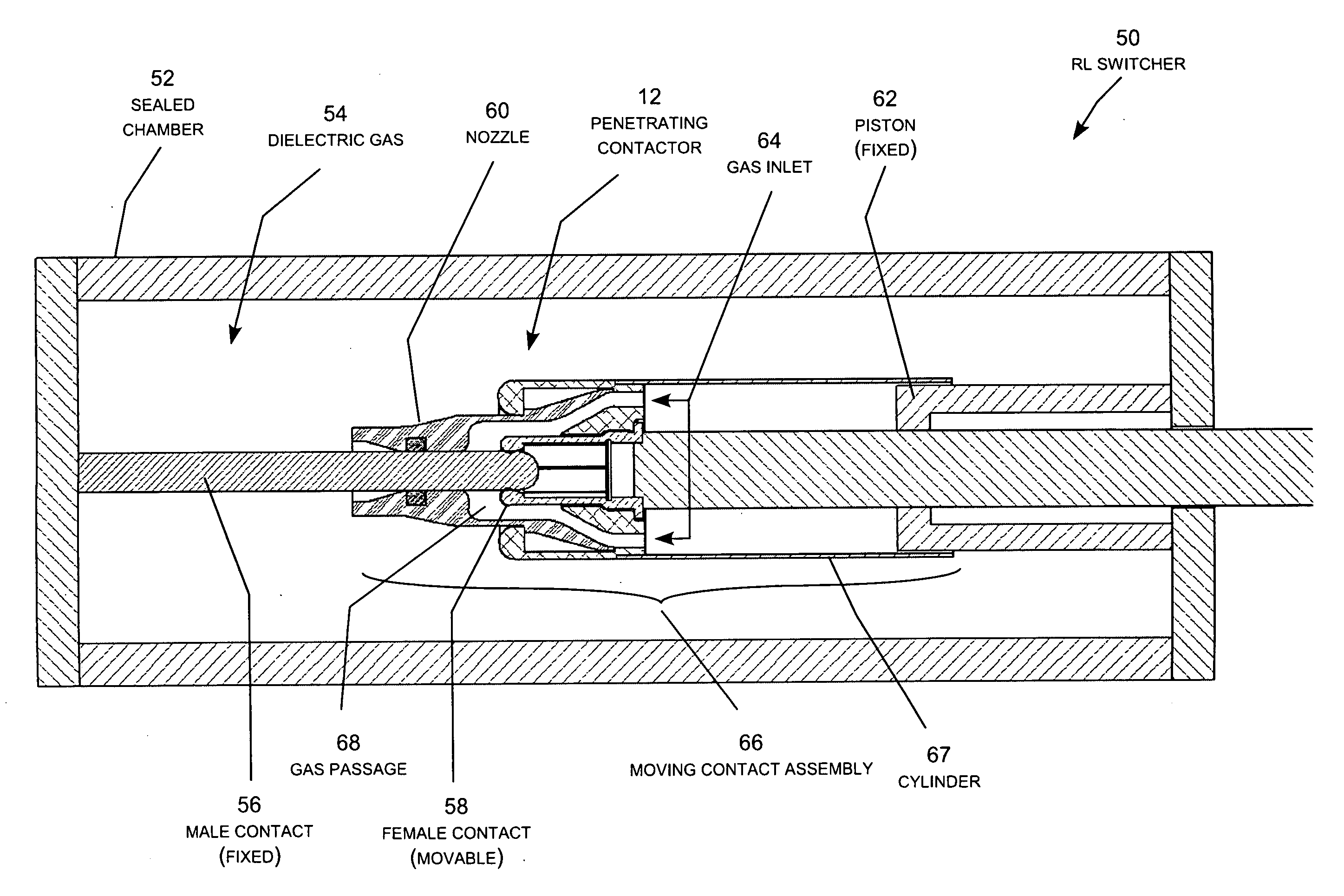
[0012]Generally described, the invention may be practiced in an electric power switch, a circuit interrupter for an electric power switch, or in a nozzle for a circuit interrupter. The circuit interrupter includes a sealed chamber containing a dielectric gas. The circuit interrupter also includes a
contactor located within the chamber having first and second contacts movable in relation to each other during an opening stroke from a closed position in which the contacts are electrically connected to close the electric power circuit to an open position in which the contacts are electrically separated to open the electric power circuit. A drive mechanism operates to move the contacts through the opening stroke and create a flow of the dielectric gas within the chamber to open the electric power circuit. The contacts are configured to form an arc extending in an arc gap direction across an arc gap between the contacts during the opening stroke. A nozzle, which is configured to direct the flow of the dielectric gas into the arc gap to extinguish the arc during the opening stroke, includes an arc extending zone in fluid communication with an arc extinguishing zone. A dielectric gas regulator restricts the flow of the dielectric gas into the arc gap during a first portion of the opening stroke to cause the arc gap to extend across the arc extending zone. The dielectric gas regulator then opens the flow of the dielectric gas into the arc gap during a second portion of the opening stroke to initially extinguish the arc after the arc has extended into the arc extinguishing zone. The arc extending zone has a sufficient length in the arc gap direction to prevent the arc from flashing over across the arc gap between the contacts after the arc has been initially extinguished.


