Lapping plate-conditioning grindstone segment, lapping plate-conditioning lapping machine, and method for conditioning lapping plate
a technology of lapping plate and grinding stone, which is applied in the field of lapping machines, can solve the problems of affecting the quality of workpieces, and requiring a long time of conditioning operation of conditioning jigs, and achieves the effect of minimal surface roughness and stable lapping for
Inactive Publication Date: 2010-07-29
SHINANO ELECTRIC REFINING
View PDF7 Cites 19 Cited by
- Summary
- Abstract
- Description
- Claims
- Application Information
AI Technical Summary
Benefits of technology
[0021]As compared with the surface conditioning of a lapping plate using a prior art conditioning jig such as a conditioning carrier made of ceramics, metal or the like and abrasive grains, the invention makes it possible to achieve within a short time conditioning of a lapping plate and simultaneously opening of spheroidal graphite holes on the lapping plate surface and formation of a uniform fine texture surface. When a workpiece is actually lapped with the lapping plate using loose abrasive grains, adequate abrasive grains are caught within opened spheroidal graphite holes on the lapping plate surface at an increased retaining force so that a stable lapping force is produced, and the fine texture surface of the lapping plate is transferred to the workpiece. Thus the workpiece is finished to a minimal surface roughness.
Problems solved by technology
Then the flatness of workpieces lapped is worsened.
Workpieces having satisfactory flatness are no longer obtained.
However, these lapping plate-conditioning jigs require a long time of conditioning operation until the lapping plate is resurfaced to the desired flatness.
Method used
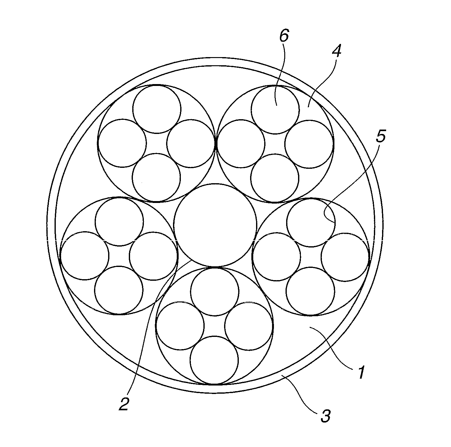
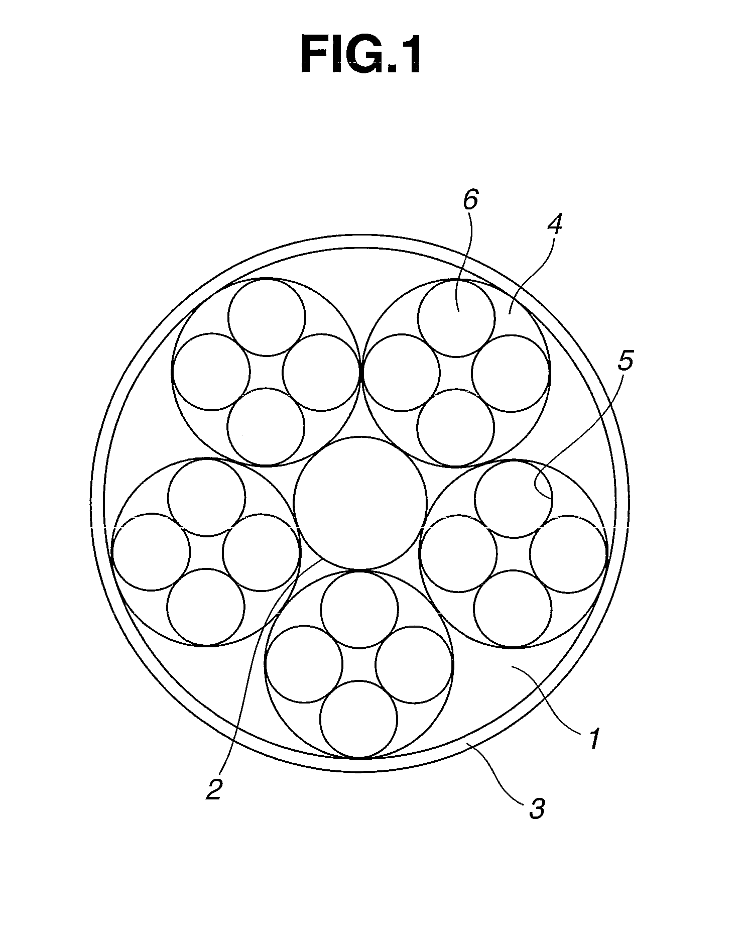
View moreImage
Smart ImageViewing Examples
Examples
example
[0063]Example and Comparative Example are given below by way of illustration and not by way of limitation.
Login to View More PUM
| Property | Measurement | Unit |
|---|---|---|
| included angle | aaaaa | aaaaa |
| Rockwell hardness | aaaaa | aaaaa |
| pore size | aaaaa | aaaaa |
Abstract
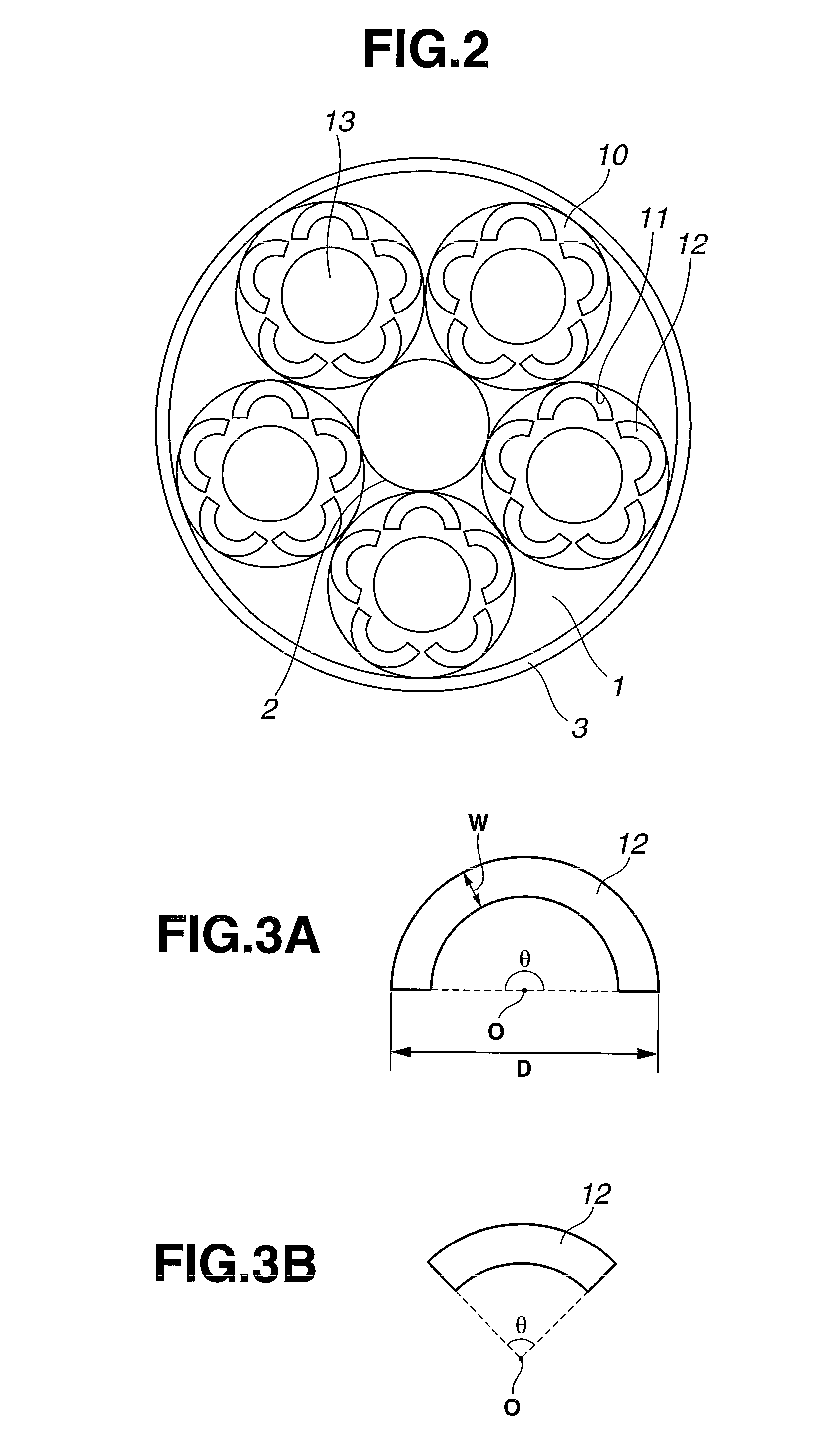
In a lapping machine comprising a lapping plate and a conditioning carrier disposed thereon, the carrier being provided with bores for receiving conditioning grindstone segments, the lapping plate is polished and conditioned by cooperatively rotating the lapping plate and the carrier and feeding loose abrasive grains to the lapping plate. The conditioning grindstone segment of a shape of arcuated trapezoid having an included angle of 180°-90° is fitted in the carrier bore.
Description
CROSS-REFERENCE TO RELATED APPLICATION[0001]This non-provisional application claims priority under 35 U.S.C. §119(a) on Patent Application Nos. 2009-015517 and 2009-170336 filed in Japan on Jan. 27, 2009, and Jul. 21, 2009, respectively, the entire contents of which are hereby incorporated by reference.TECHNICAL FIELD[0002]This invention generally relates to a lapping machine comprising a lapping plate and a conditioning carrier disposed on the lapping plate, the carrier being provided with at least one bore for receiving a conditioning grindstone segment, wherein the lapping plate is conditioned by cooperatively rotating the lapping plate and the carrier and feeding loose abrasive grains to the lapping plate. More particularly, it relates to a grindstone segment for conditioning the lapping plate, and a lapping machine and method for conditioning the lapping plate.BACKGROUND ART[0003]In the prior art, a lapping machine as shown in FIG. 1 is used for lapping workpieces such as silic...
Claims
Login to View More Application Information
Patent Timeline
 Patent Type & Authority Applications(United States)
IPC IPC(8): B24B37/04B24B7/04B24B41/06B24B53/00B24B53/12B24B53/013B24B53/02B24D3/32B24D7/06
CPCB24B53/013B24D7/06B24B53/12B24B53/02B24B53/017H01L21/304
Inventor YASUOKA, KAISHIMIZU, TSUYOSHIKAZAMA, KENICHI
Owner SHINANO ELECTRIC REFINING
Features
- R&D
- Intellectual Property
- Life Sciences
- Materials
- Tech Scout
- Unparalleled Data Quality
- Higher Quality Content
- 60% Fewer Hallucinations
Learn More Browse by: Latest US Patents, China's latest patents, Technical Efficacy Thesaurus, Application Domain, Technology Topic, Popular Technical Reports.
© 2025 PatSnap. All rights reserved.Legal|Privacy policy|Modern Slavery Act Transparency Statement|Sitemap|About US| Contact US: help@patsnap.com


