
Hetero-structure field effect transistor, integrated circuit including a hetero-structure field effect transistor and method for manufacturing a hetero-structure field effect transistor

a hetero-structure field and transistor technology, applied in transistors, semiconductor devices, electrical devices, etc., can solve the problems of large leakage current of semiconductor devices, relatively high resistive losses, and inability to operate devices by leakage curren

Active Publication Date: 2010-07-29
NXP USA INC
View PDF14 Cites 12 Cited by
  • Summary
  • Abstract
  • Description
  • Claims
  • Application Information

AI Technical Summary

Benefits of technology

[0007]Specific embodiments of the invention are set forth in the dependent claims. These and other aspects of the invention will be apparent from and elucidated with reference to the embodiments described hereinafter.

Problems solved by technology

However, a disadvantage of the semiconductor device disclosed in this publication is that the semiconductor device exhibits a large leakage current since, although it is described that a 2 dimensional electron gas (2DEG) is obtained, the flowing electrons are not confined to a 2-dimensional region but can actually flow from source to drain over the whole thickness of the lower semiconductor layer, even when a negative voltage is applied at the gate electrode.
However, a disadvantage of the device disclosed in this ‘Ben-Yaacov’ publication is that in operation it exhibits relatively high resistive losses and the high leakage current does not enable to operate the device in a off-state configuration up to a breakdown source-drain voltage.

Method used


Image

  • Hetero-structure field effect transistor, integrated circuit including a hetero-structure field effect transistor and method for manufacturing a hetero-structure field effect transistor
  • Hetero-structure field effect transistor, integrated circuit including a hetero-structure field effect transistor and method for manufacturing a hetero-structure field effect transistor

Examples


Embodiment Construction

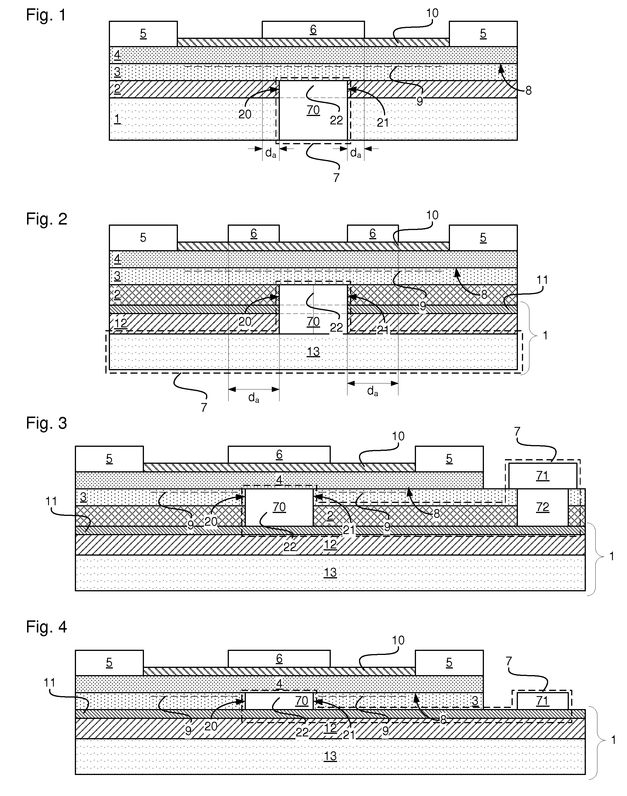
[0013]Referring to FIGS. 1-4 examples of a hetero-structure field effect transistor (HFET), which may also be referred to as a high electron mobility transistor (HEMT), are shown therein. As shown in the example, the HFET may include one or more first contacts 5, The HFET may further include second contact 7. The HFET may for example be implemented as a high power switch which can control currents at high voltages, for example at voltages of 50 V or more and / or 1000 V of less.

[0014]The HFET may include a hetero-junction structure which connects the first contact 5 to the second contact 7. As shown, the hetero-junction structure may include a first layer 3 made from a first semiconductor material and a second layer 4 made from a second semiconductor material. An interface 8 may be present at which the first layer 3 and the second layer 4 are in contact with each other, along the interface 8 a two dimensional electron gas (2DEG) 9 may be formed in a part of the first layer 3 directly ...


PUM


Abstract

A hetero-structure field effect transistor (HFET). The HFET may include a first contact and a second contact and a hetero-junction structure. The hetero-junction structure may include a first layer made from a first semiconductor material and a second layer made from a second semiconductor material. An interface at which the first layer and the second layer are in contact with each other may be provided, along which a two dimensional electron gas (2DEG) is formed in a part of the first layer directly adjacent to the interface, for propagating of electrical signals from the first contact to the second contact or vice versa. The transistor may further include a gate structure for controlling a conductance of the channel; a substrate layer made from a substrate semiconductor material, and a dielectric layer separating the first layer from the substrate layer. The second contact may include an electrical connection between the substrate layer and the first layer. The electrical connection may include a passage through the dielectric layer filled with an electrically conducting material which is electrically connected to the first layer.

Description

FIELD OF THE INVENTION[0001]This invention relates to a hetero-structure field effect transistor, to an integrated circuit including a hetero-structure field effect transistor and to a method for manufacturing a hetero-structure field effect transistor.BACKGROUND OF THE INVENTION[0002]A hetero-structure field effect transistor is known from International patent application publication WO 2005 / 079370. The hetero-structure field effect transistor includes an AlGaN / GaN interface that obtains a high current carrying channel. The bidirectional switch operates with at least one gate that prevents or permits the establishment of a two dimensional electron gas to form the current carrying channel for the bidirectional switch.[0003]From International patent application publication WO 2006 / 052052 a semiconductor device is known. The semiconductor device has a base plate made from n-doped GaN (n-GaN) with a low resistance. A drain electrode is formed on the base plate. A top surface of the sem...

Claims


Application Information

Patent Timeline
Patent Type & Authority Applications(United States)
IPC IPC(8): H01L29/80H01L21/337H01L29/02
CPCH01L29/1029H01L29/7788H01L29/7787H01L29/2003
Inventor RENAUD, PHILIPPE
Owner NXP USA INC
Learn More