
Surface marked articles, related methods and systems

a surface marking and surface technology, applied in the field of articles, can solve the problems of insufficient aesthetic appeal of synthetic materials with ink-jet graphics alone, lack of textural feel inherent in many natural materials, and lack of attractive appearance and authenticity of natural materials, etc., and achieve the effect of high quality

Inactive Publication Date: 2010-07-22
MASONITE CORP
View PDF50 Cites 49 Cited by
  • Summary
  • Abstract
  • Description
  • Claims
  • Application Information

AI Technical Summary

Benefits of technology

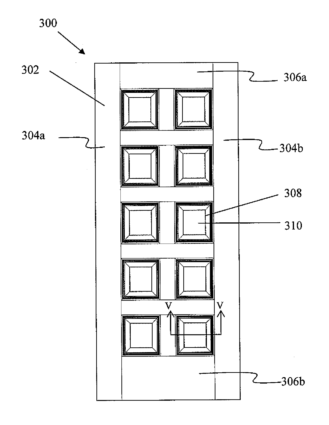
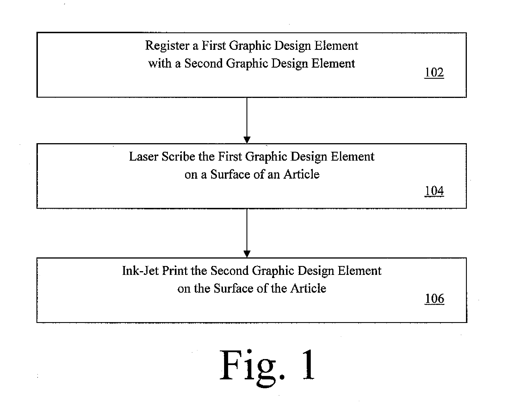
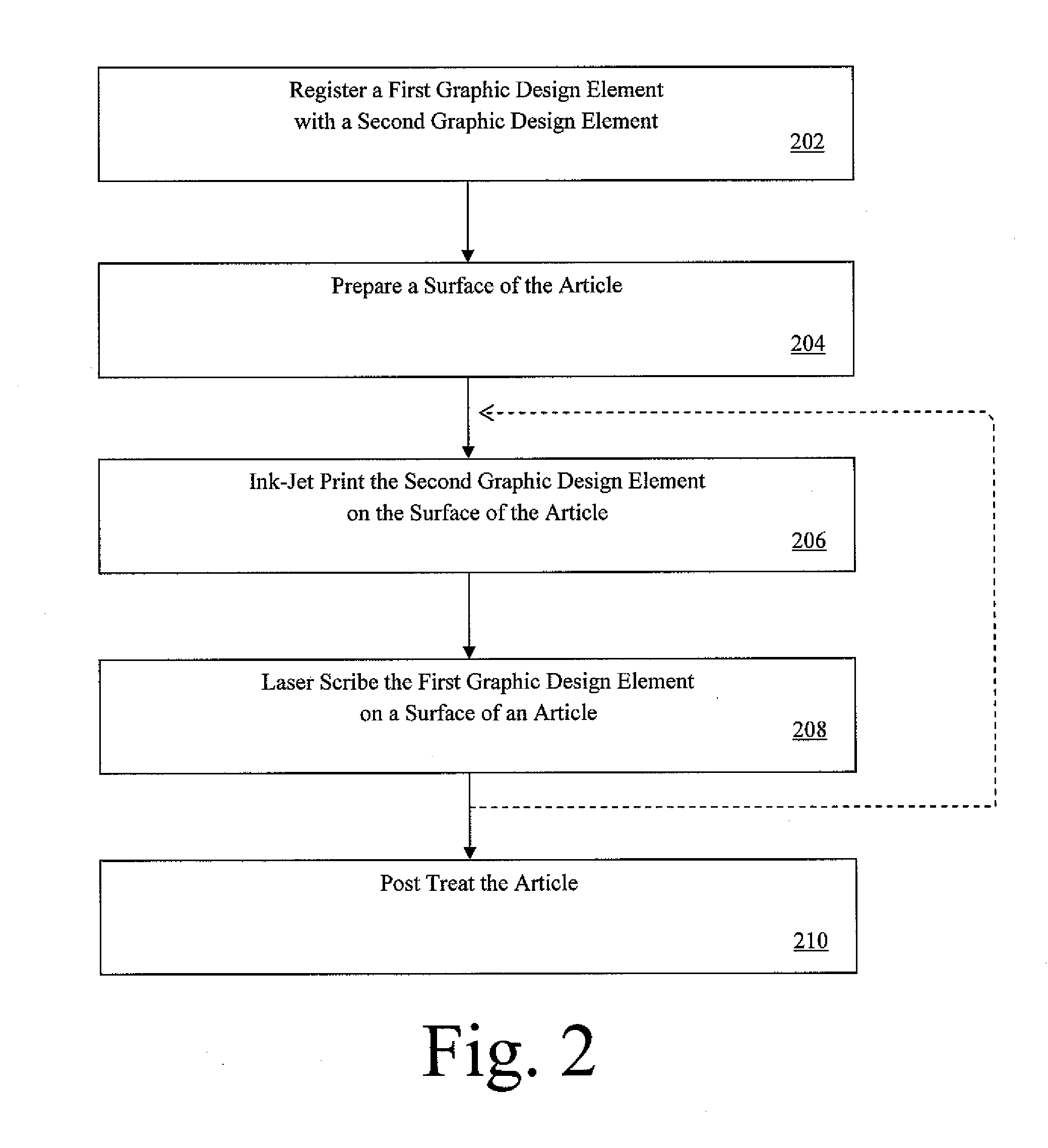
[0008]A first aspect of the invention provides a method of surface marking an article, such as a door, featuring registering a first graphic design element with a second graphic design element, laser marking the first graphic design element in a surface of the article, and ink-jet printing a second graphic design element on the surface of the article, the first and second graphic design elements being registered with one another to provide a high quality overall graphic design that simulates visually and texturally a natural material.
[0009]A second aspect of the invention relates to an article featuring a first graphic design element laser-marked on a surface of the article, and a second graphic design element ink-jet printed in a predetermined orientation or association with the first graphic design element on the article surface to provide a high quality overall graphic design that simulates visually and texturally a natural material.
[0010]A third aspect of the invention relates to a system for surface marking an article. The system includes a laser marking apparatus and an ink jet printing apparatus for printing first and second graphic design elements, respectively, in a predetermined orientation or association relative to one another to provide a high quality overall graphic design that simulates visually and texturally a natural material.

Problems solved by technology

While synthetic materials may provide substantial cost savings over natural materials such as wood, stone, and ceramic, synthetic materials lack the attractive appearance and the authenticity of natural materials.
Synthetic materials with ink-jet graphics alone, however, may not have sufficient aesthetic appeal to more discriminate consumers.
Ink-jet printed surfaces lack a textural feel inherent in many natural materials, and vital to their appearance.
Additionally, cylinder printing and foil overlay techniques suffer from various problems when they are utilized on non-uniform surfaces.
Cylinder printing techniques may fail to contact such surface features below the principal planar surface.
Foil overlays, on the other hand, may completely hide or conceal these features.
Other surface decorative processes such as sandblasting and veneering have their drawbacks as well, such as high cost.
Nonetheless, lasers alone remain insufficient for generating realistic simulations of natural surfaces such as wood, stone, or other natural materials.
Even with the addition of a painted ground coat, laser-treated surfaces lack certain pattern elements of authentic natural materials, such as wood graining in the case of wood reproductions, or mosaics of interlocking mineral grains in the case of natural stone reproductions.
Additionally, various restraints create difficulties with using conventional lasers to create complex graphics.
Due to the relatively limited power capacity of conventional lasers, and the economic expense of operating lasers at high energy outputs, lasers typically are operated at relatively low power levels for manufacturing articles such as building components.
These power concerns, coupled with the high density of certain work pieces such as engineered wood composite, place restrictive limitations on the rate at which the laser beam is able to create a graphic design in the surface of a synthetic work piece.
Creation of expansive or particularly complex graphics may require prolonged efforts that make high capacity manufacturing economically infeasible.

Method used


Image

  • Surface marked articles, related methods and systems
  • Surface marked articles, related methods and systems
  • Surface marked articles, related methods and systems

Examples


examples

[0089]To demonstrate the influence of substrate material and graphic image pattern on laser power and scan speed, the experiments set forth in Table I below were carried out on various substrates.

TABLE ILaserLaser ScanGraphicPowerSpeedSubstrateImage(Watts)(m / s)PVC CompositeCedar175010Polyethylene wood compositeCedar250010Polyethylene wood compositeMaple200010Polyethylene wood compositeLeopard175010HardboardWalnut250015Painted MDF (2 paint layers)Simple Oak250040Medium Density FiberboardRose Pedals250015(MDF)Medium Density FiberboardSimple150022(MDF)WalnutMedium Density FiberboardOak Cross150022(MDF)GrainPainted Hardboard (2 paintMaple137515layers)Painted Hardboard (1 paintSimple Oak250028layer)Primed HardboardSimple Oak250032PVCCedar250010Reaction-Injected MoldedCedar225010Plastics

[0090]The effects of controller speed on laser power change width for two separate graphic images are demonstrated by Tables II and III below. Table II contains data for 32 laser lines per inch and Table I...


PUM

PropertyMeasurementUnit
weight percentaaaaaaaaaa
angleaaaaaaaaaa
scan speedsaaaaaaaaaa

Abstract

A method of surface marking an article, especially a building product, is provided. One described method includes the steps of laser marking a first graphic design element on a surface of an article and ink-jet printing a second graphic design element in registry with the first graphic design element on the surface of the article to create a high quality overall graphic design. Also provided are articles made according to this method, and systems for carrying out the method.

Description

CROSS-REFERENCE TO RELATED PATENT APPLICATIONS AND CLAIM TO PRIORITY[0001]This patent application claims the benefit of U.S. Provisional Application No. 61 / 145,316, entitled “Surface Marked Articles and Related Methods,” and filed Jan. 16, 2009, incorporated herein by reference and to which priority is claimed.FIELD OF THE INVENTION[0002]The present invention relates to articles, especially doors and door skins, surface marked by laser marking and ink-jet printing to provide high quality decorative products. The present invention further relates to methods and systems for making such articles.BACKGROUND OF THE INVENTION[0003]Residential and commercial building products are often made of an engineered composite material, including cellulosic composite materials such as medium to high density fiberboard and particleboard, as well as other “synthetic” materials such as laminates, veneers, and reinforced polyester sheet molding compound (SMC), to name a few. Such products find various a...

Claims


Application Information

Patent Timeline
Patent Type & Authority Applications(United States)
IPC IPC(8): D05B3/06
CPCB41J3/407B41J3/4073B41J3/546B41M3/008B41M5/0047B41M5/24
Inventor RUGGIE, MARKCOGHLAN, HENRYHEUSER, HALLIECARTER, CHASE
Owner MASONITE CORP
Learn More