
Projection type display device

a display device and projection type technology, applied in projectors, lighting and heating devices, instruments, etc., can solve problems such as blacking and degradation of light sources brightness, problems such as whitening and life property degradation, and complicated lighting conditions of light sources, so as to achieve high quality and reliability, accurate and reliable control of temperature managemen

Inactive Publication Date: 2010-07-15
PANASONIC CORP
View PDF5 Cites 8 Cited by
  • Summary
  • Abstract
  • Description
  • Claims
  • Application Information

AI Technical Summary

Benefits of technology

"The present invention provides a projection type display device that uses multiple light sources and has a cooling unit with a ventilating fan for controlling the temperature management of the light sources. The device also includes a flow direction adjusting unit and a control unit for adjusting the blow-off positions of the fan based on the posture information of the light sources. This results in highly accurate and reliable control of temperature management, which helps to prevent issues such as whitening of the light sources, life property degradation, blacking, and brightness degradation. Therefore, the present invention provides a multipurpose projection type display device with high quality and reliability."

Problems solved by technology

If the temperature of the light source lamp rises extremely, problems such as whitening and life property degradation will occur.
To the contrary, when the temperature of the light source lamp is extremely low, it causes problems such as blacking and degradation in the brightness of the light source.
On the other hand, the conditions for lighting the light sources will be complicated.
Therefore, it is not possible to handle the change in the temperature distribution inside the light source unit by uniformly supplying cool air to the light sources unit from a cooling fan through certain air outlets, so that the cooling efficiency declines.
As a result, maintaining the temperature of the light sources within a desired range becomes difficult and the possibility of a breakdown increases.
To prevent this problem, it is necessary to increase the scale of the cooling system, which results in an increase in the size of the device and in a problem in terms of cost.

Method used


Image

  • Projection type display device
  • Projection type display device
  • Projection type display device

Examples


embodiment

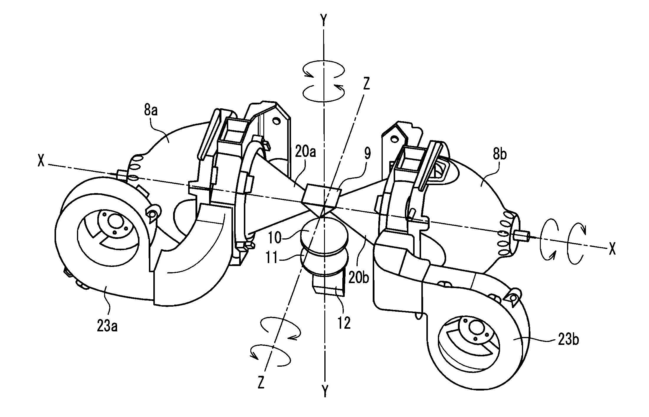
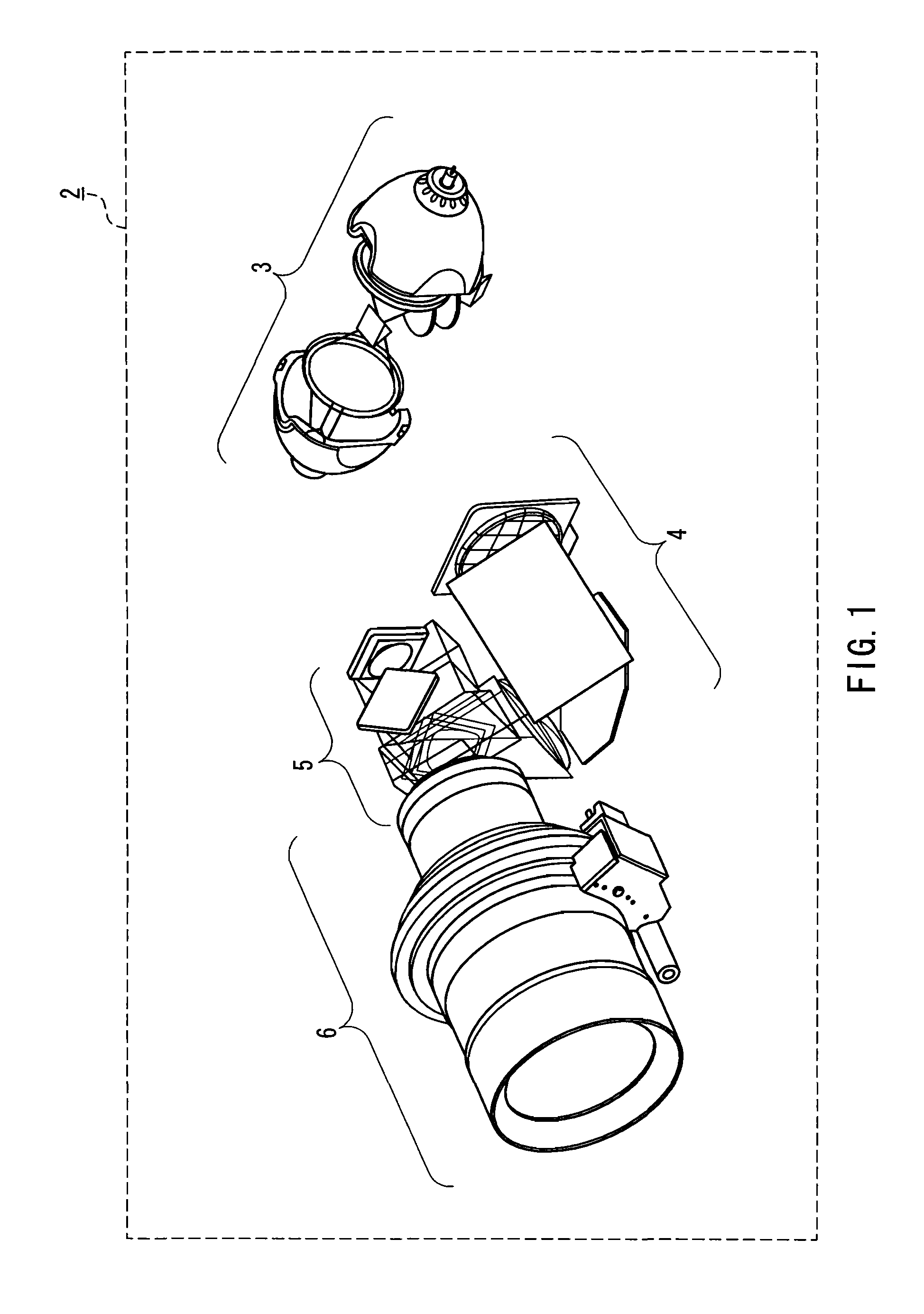
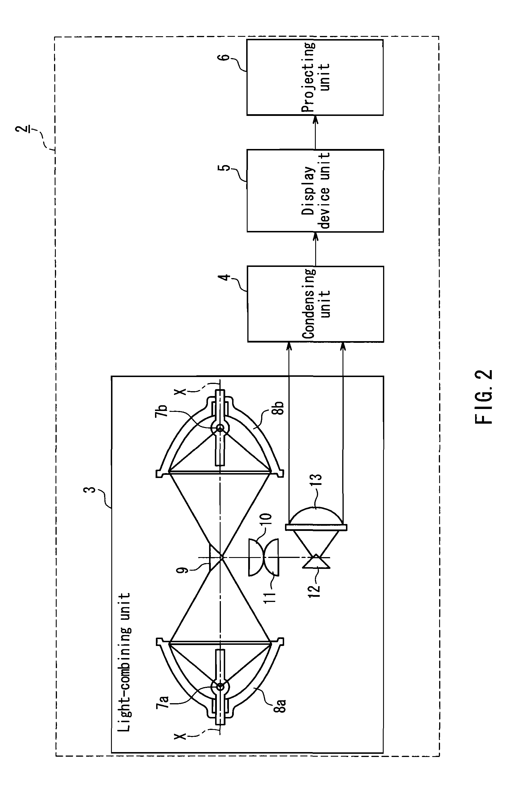
[0034]First, an optical system forming the projection type display device (hereinafter abbreviated as the device) according to an embodiment of the present invention will be described with reference to FIGS. 1 and 2. FIG. 1 is a perspective view showing a schematic configuration of the optical system 2 of the device. FIG. 2 is a diagram showing a basic configuration of a light-combining unit 3 for combining two light beams in the optical system 2.

[0035]The optical system 2 includes the light-combining unit 3, a condensing unit 4, a display device unit 5 and a projecting unit 6. As shown in FIG. 2, the light-combining unit 3 combines output light beams from two light source lamps 7a and 7b. Output light from the light-combining unit 3 is propagated to the display device 5 by the condensing unit 4. The display device unit 5 is composed of an image display device such as DMD (Digital Micromirror Device). The projecting unit 6 projects an image by the use of output light from the displa...


PUM


Abstract

A projection type display device including: a plurality of light sources; a display device; a light-combining unit for combining output light beams from the plurality of light sources; a condensing unit for propagating an output light beam from the light-combining unit to the display device; a projecting unit for projecting an image with the use of an output light beam from the display device; and a cooling unit having a ventilating fan and disposed on each of the plurality of light sources. The projection type display device further includes a flow direction adjusting unit for switching blow-off positions where air from the fan is discharged and a control unit for controlling switching of the blow-off positions operated by the flow direction adjusting unit. The control unit controls the flow direction adjusting unit to switch the blow-off positions on the basis of posture information on at least one of an inclination angle of an optical axis of the plurality of light sources and a rotation angle about the optical axis. In a configuration using a plurality of light sources, reliable control of temperature management of the light sources is performed and problems, such as whitening of the light sources, life property degradation, blacking and brightness degradation are suppressed.

Description

BACKGROUND OF THE INVENTION[0001]1. Field of the Invention[0002]The present invention relates to projection type display devices such as a projector, and particularly to a projection type display device using a plurality of light sources and provided with a cooling system that can cool the light sources adequately.[0003]2. Description of Related Art[0004]A projection type display device such as a projector has been known as a device for obtaining an image on a big screen. The projection type display device modulates light from a light source lamp with a video signal so as to form an optical image and radiates, by using an image display device such as DMD (Digital Micromirror Device) or a liquid crystal, thereby projecting the optical image in a magnified manner on the screen by the use of a projection lens.[0005]The light source lamp is filled with mercury, a rare gas, a metal halide and the like. When a predetermined voltage is applied to the electrode in the light source lamp, a d...

Claims


Application Information

Patent Timeline
Patent Type & Authority Applications(United States)
IPC IPC(8): G03B21/16
CPCG03B21/16F21V29/02F21V29/67
Inventor NAKAJIMA, YOSHINOBU
Owner PANASONIC CORP
Learn More