
Premixed partial oxidation syngas generation and gas turbine system

a gas turbine and partial oxidation technology, applied in the direction of efficient propulsion technologies, machines/engines, lighting and heating apparatus, etc., can solve the problems of complex combustion process, high catalyst cost, and common combustion instabilities, so as to facilitate mixing and facilitate mixing

Inactive Publication Date: 2010-07-15
GENERAL ELECTRIC CO
View PDF33 Cites 19 Cited by
  • Summary
  • Abstract
  • Description
  • Claims
  • Application Information

AI Technical Summary

Benefits of technology

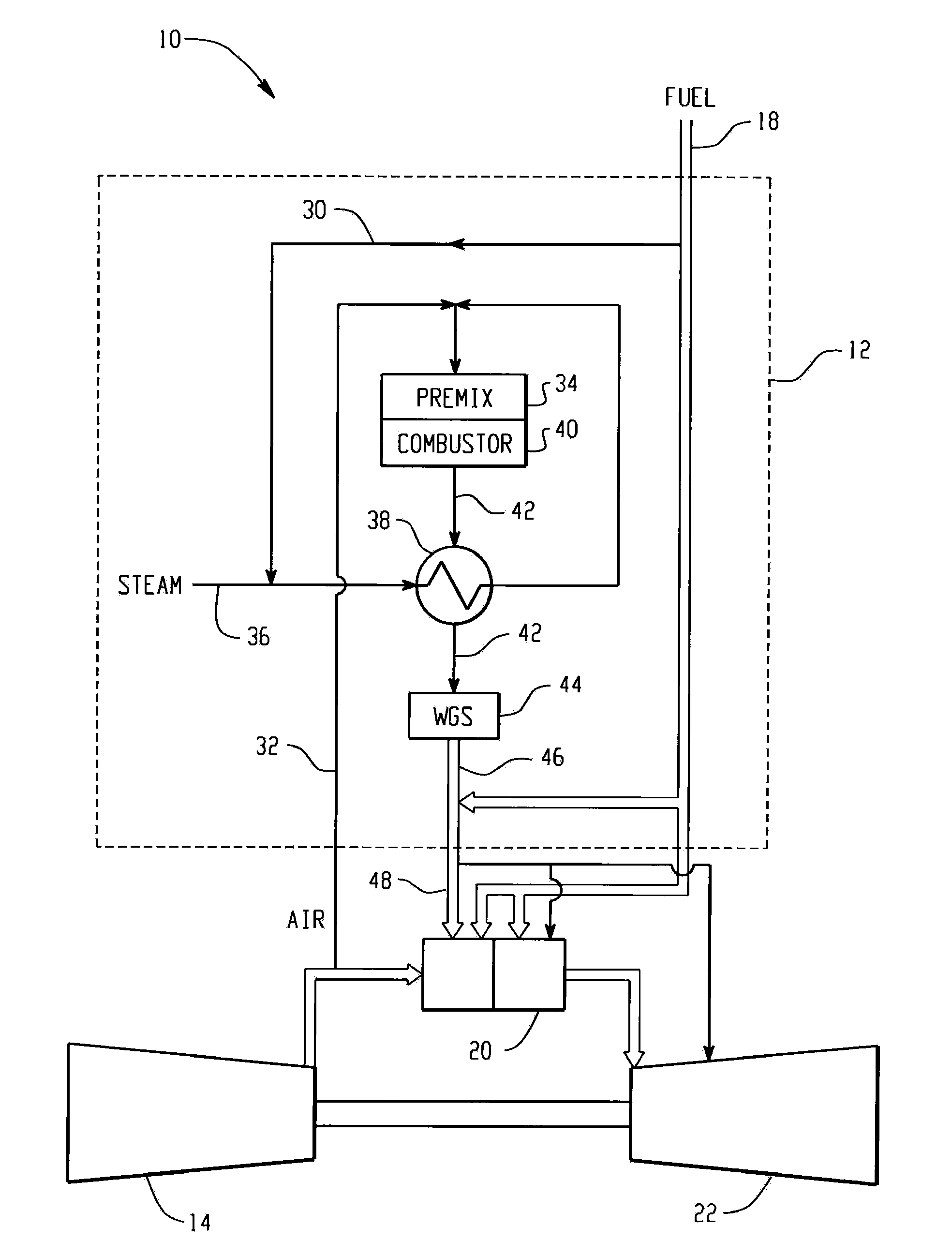
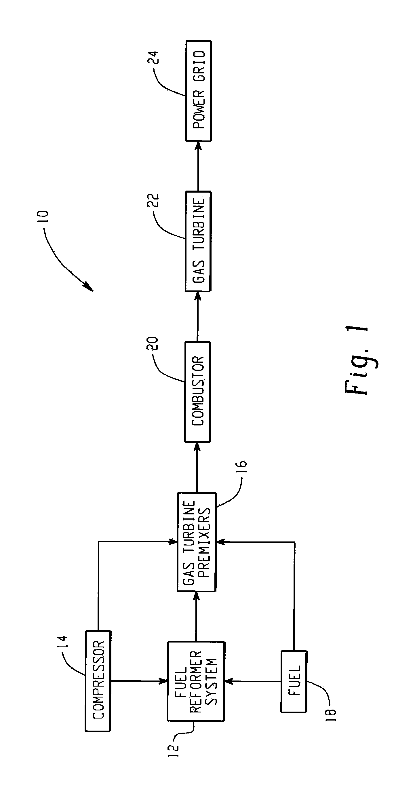
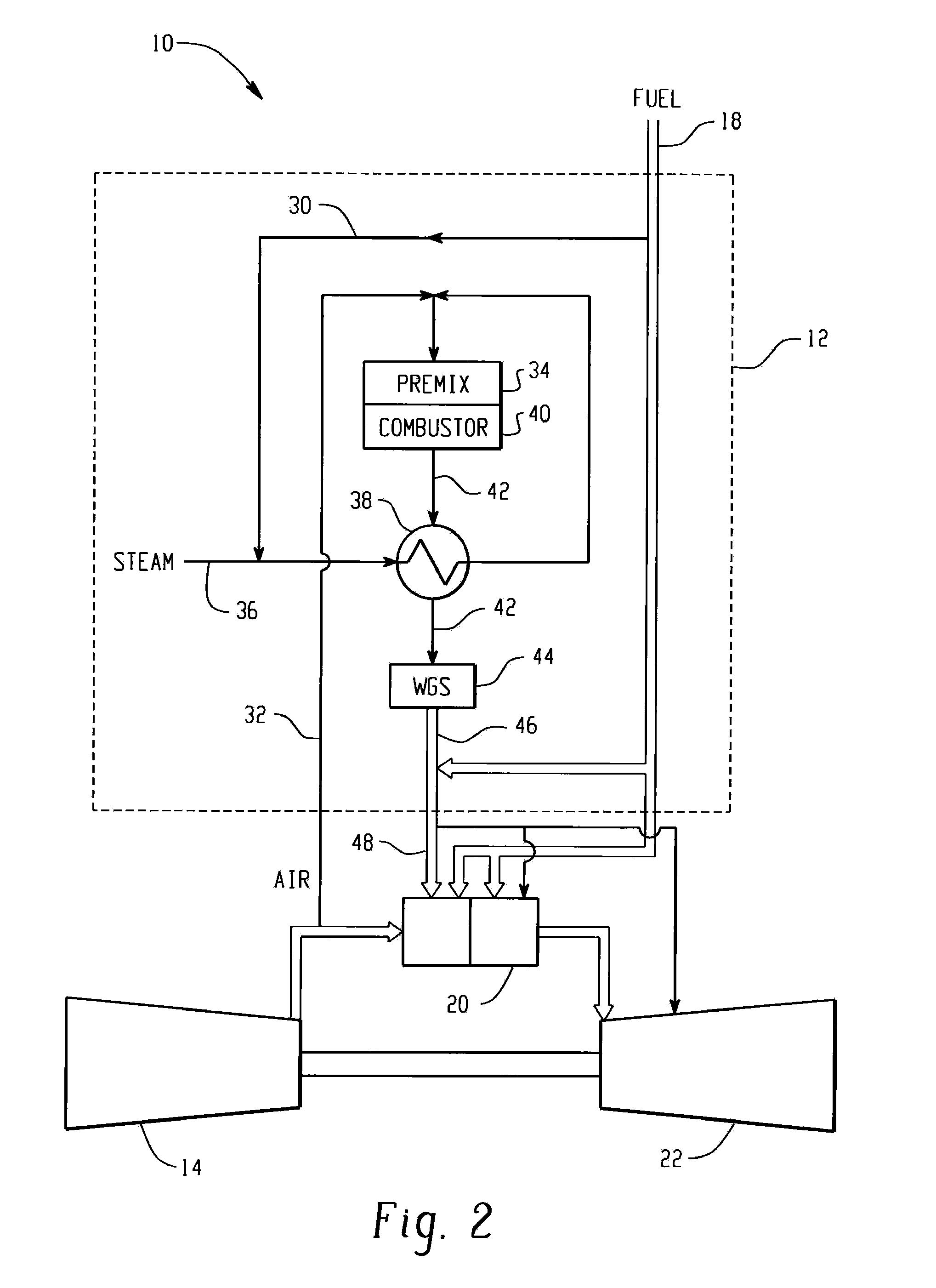
[0006]Briefly, according to one embodiment, a gas turbine system is provided. The gas turbine system includes a fuel reformer system comprising a fuel inlet configured to receive a fuel slipstream; an oxygen inlet configured to introduce an oxygen slipstream; a preconditioning zone configured to pretreat the fuel slipstream; a mixing zone comprising a premixing device configured to facilitate mixing of the fuel slipstream and the oxygen slipstream to form a gaseous premix; a reaction zone configured to generate a syngas from the gaseous premix; and a quench zone configured to mix a fuel stream into the syngas to form a hydrogen-enriched fuel mixture; and a gas turbine configured to receive the fuel mixture.
[0007]In another embodiment, a gas turbine system includes an intake section; a compressor section downstream from and in fluid communication with the intake section; a combustor section comprising a primary combustion system downstream from and in fluid communication with the compressor section; a secondary comb...

Problems solved by technology

However, combustion instabilities, also known as combustion dynamics, are commonly encountered in development of low emissions gas turbine engines.
Combustion dynamics in the form of fluctuations in pressure, heat-release rate, and other perturbations in flow may lead to problems such as lean blow out, structural vibration, excessive heat transfer to a chamber, and consequently lead to failure of the system.
However, such techniques can require expensive catalysts and can be large and complex making them hard to incorporate in an existing combustion system.

Method used


Image

  • Premixed partial oxidation syngas generation and gas turbine system
  • Premixed partial oxidation syngas generation and gas turbine system
  • Premixed partial oxidation syngas generation and gas turbine system

Examples


Embodiment Construction

[0022]As described in detail below, embodiments of the present disclosure provide gas turbine systems incorporating a fuel reformer system. The systems and techniques described herein function to enhance power output and efficiency of gas turbine systems, such as staged gas turbine systems and reheat gas turbine systems. The reformer system utilized in the gas turbine systems is configured to provide mixing and reacting of a slipstream of fuel with a slipstream of oxygen to increase a concentration of hydrogen through premixed partial oxidation combustion. The introduction of hydrogen into the fuel allows lowering of a lean blow out point and enables reduction in combustion dynamics for the gas turbine system. The term “combustion dynamics” used herein refers to fluctuations in oxygen pressure, temperature, heat release and unsteady flow oscillations that effect operation of an engine, including a gas turbine. Further, the term ‘lean blow out point’ used herein refers to a point of ...


PUM


Abstract

A gas turbine system includes a fuel reformer system comprising a fuel inlet configured to receive a fuel slipstream; an oxygen inlet configured to introduce an oxygen slipstream; a preconditioning zone configured to pretreat the fuel slipstream; a mixing zone comprising a premixing device configured to facilitate mixing of the fuel slipstream and the oxygen slipstream to form a gaseous premix; a reaction zone configured to generate a syngas from the gaseous premix; a quench zone configured to mix a fuel stream into the syngas to form a hydrogen-enriched fuel mixture; and a gas turbine configured to receive the fuel mixture.

Description

BACKGROUND OF THE INVENTION[0001]The invention relates generally to gas turbine combustion systems, and more particularly to fuel reformers based on premixed partial oxidation combustion for improving the efficiency of the gas turbine systems.[0002]There is a drive within the industry to produce new turbines that will operate at high efficiency without producing undesirable air polluting emissions. The primary air polluting emissions usually produced by turbines burning conventional hydrocarbon fuels are oxides of nitrogen, carbon monoxide and unburned hydrocarbons. The oxidation of molecular nitrogen in air breathing engines can be highly dependent upon the maximum temperature in the combustion system reaction zone and the residence time for the reactants at the maximum temperatures reached within the combustor. The level of thermal nitrogen oxides (NOx) formation can be minimized by maintaining the reaction zone temperature below the level at which thermal NOx is formed or by main...

Claims


Application Information

Patent Timeline
IPC IPC(8): F02C6/18F02C7/22
CPCF02C3/30F02C7/22F05D2270/082F23C6/04F23C2900/03002Y02T50/677F23R3/286F23R2900/00002Y02E20/14Y02E20/16F23C2900/9901Y02T50/60
Inventor HAYNES, JOEL MEIER
Owner GENERAL ELECTRIC CO
Learn More