
MRI compatible electrical lead for an implanted electronic medical device

Inactive Publication Date: 2010-07-08
KENERGY INC
View PDF22 Cites 88 Cited by
  • Summary
  • Abstract
  • Description
  • Claims
  • Application Information

AI Technical Summary

Benefits of technology

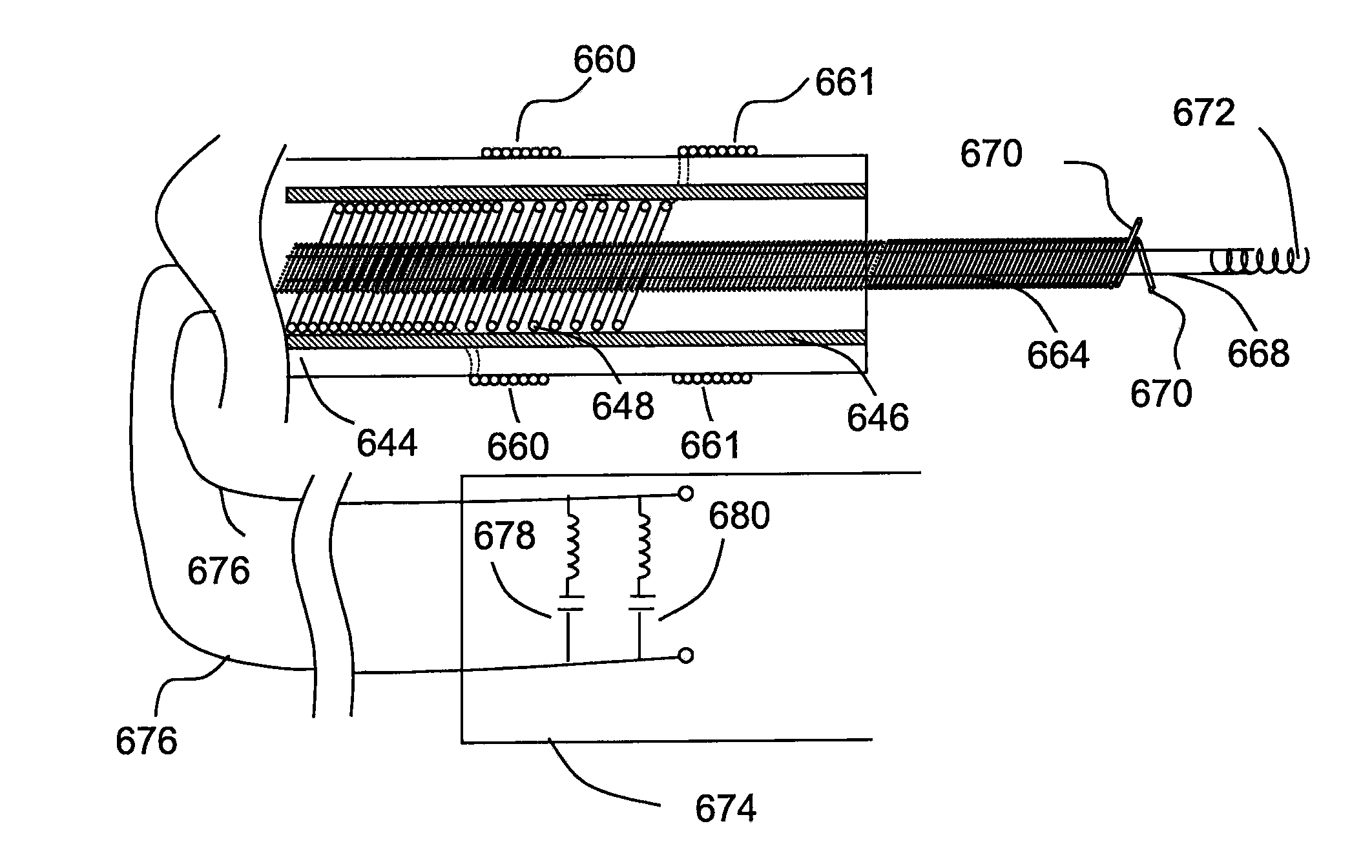
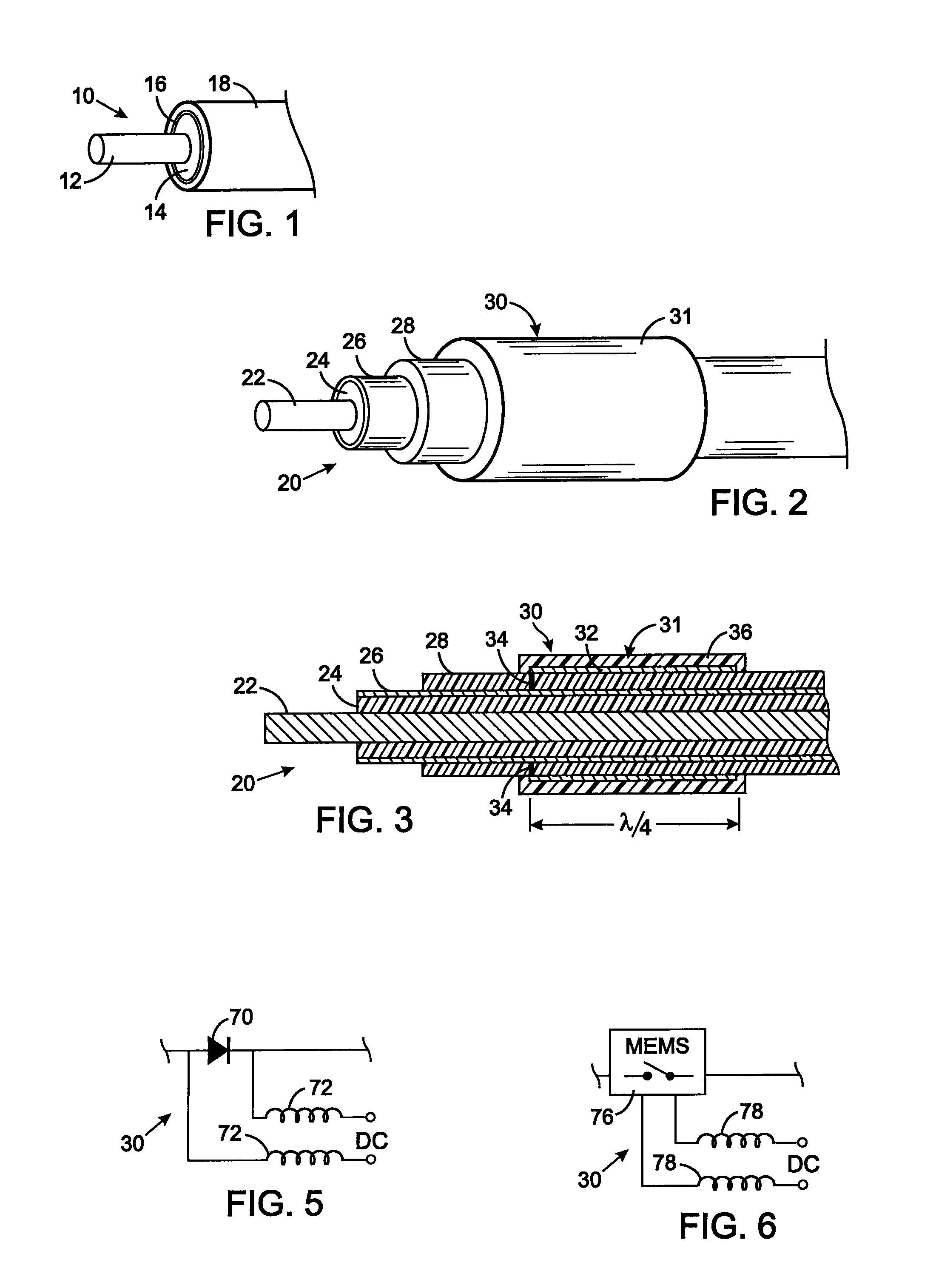
[0029]The present invention is directed toward an electrical lead for a medical device that is adapted for implantation in an animal and that is compatible with a magnetic resonance imaging (MRI) scanner which responds to signals at a Larmor frequency of tissue in the animal. The electrical lead comprises a first coil that includes at least one first insulated conductor wound along a length of the lead. The first coil has a first inductance and a first capacitance, wherein the first inductance and the first capacitance cause the first coil to act as a first parallel resonator tuned to the Larmor frequency. The first parallel resonator mitigates signals at the Larmor frequency that otherwise would travel along the first coil.
[0031]As an additional aspect, the electrical lead has a second coil which includes at least one second insulated conductor wound along a length of the lead. The second coil has a second inductance and a second capacitance that cause the second coil to act as a second parallel resonator tuned to the Larmor frequency. The second parallel resonator mitigates signals at the Larmor frequency that otherwise would travel along the second coil. The first coil and second coil may be wound in the same or opposite directions along the length of the electrical lead.

Problems solved by technology

First, incompatible implant components induce susceptibility difference, which destroys DC magnetic field homogeneity, thereby affecting the imaging performance of the magnetic resonance (MR) scanner.
Second, conductive materials present an opportunity for eddy currents to form, which currents generate heat that adversely affects patient safety and degrade the scanner performance by field distortion.
Third, the MRI fields may ruin the implanted device.
Fourth, the incompatible implant material can potentially cause serious internal injuries to the patient.
Obviously the surrounding tissue adjacent the implantable device will be damaged in this case and the health of the patient will be compromised.
In addition, metallic components can become hot and burn the patient.
Due to MRI field induced torque and movement of the implant, its components may become disconnected making the device inoperable.
Ferrites and other ferromagnetic material in transformer cores, inductors and other electronic components become saturated, thereby jeopardizing the function of the medical device.
Heating causes electronic components to operate out of specification.
The homogeneity of the magnetic resonance imager's DC magnetic field will be distorted, destroying spectral resolution and geometric uniformity of the image.
The inhomogeneous field also results in rapid de-phasing of the signal inside the excited volume of the patient.
Even if the implanted device does not contain any ferromagnetic materials, the magnetic susceptibility of the device may be different than that of the surrounding tissue, giving rise to local distortion and signal dropouts in the image, close to the device.
This movement can be unsafe for the surrounding tissue.
Resultant muscle twitching can be so intense as to be painful.
The eddy currents may be strong enough to damage electronic circuits and destroy the implanted device.
The eddy currents also locally distort the linearity of the gradient fields and de-phase the spin system, resulting in image distortion and signal dropouts.
Non-metallic implantable devices do not have these issues, but can still distort the uniformity of the RF field if the permittivity of the device is different than that of the surrounding tissue.
This distortion is especially strong at radio frequencies above 100 MHz.
Localized high voltages and currents in the medical device may cause components to fail either due to high voltage arcing, or due to dissipated power and heat.
This includes connections that become unsoldered due to the heat.
The device may generate pulsed voltages at unwanted times and locations in the leads of a cardiac pacemaker.
Local distortion of the uniformity of the B-field component of the RF field will give rise to flip angle variation and creates contrast and signal-to-noise ratio (SNR) inhomogeneity.
If the specific absorption rate exceeds legal limits, images cannot be made using magnetic resonance scanners.
Lower bulk resistivity results in shallower electromagnetic (EM) skin depths in the conductor.
Choice of a plating material can degrade performance (increase attenuation) if its bulk resistivity is greater than that of the body of the wire.
If such a conductor is placed inside the E field of an MRI RF transmit coil, there will be RF energy deposition in the tissue surrounding the wire resulting in elevated temperatures that may result in physical injury to the patient.
An implantable enclosure with an integrated antenna provides another challenge for MRI compatibility.
Such noise can potentially interfere with the function of the device as it may cause corruption of the physiological data that is being gathered.
A disadvantage of this method is that in order for a power or communication antenna to work, the antenna has to be positioned outside of that enclosure, as an internal antenna would not be able to receive or transmit effectively through the Faraday shield.

Method used


Image

  • MRI compatible electrical lead for an implanted electronic medical device
  • MRI compatible electrical lead for an implanted electronic medical device
  • MRI compatible electrical lead for an implanted electronic medical device

Examples


Embodiment Construction

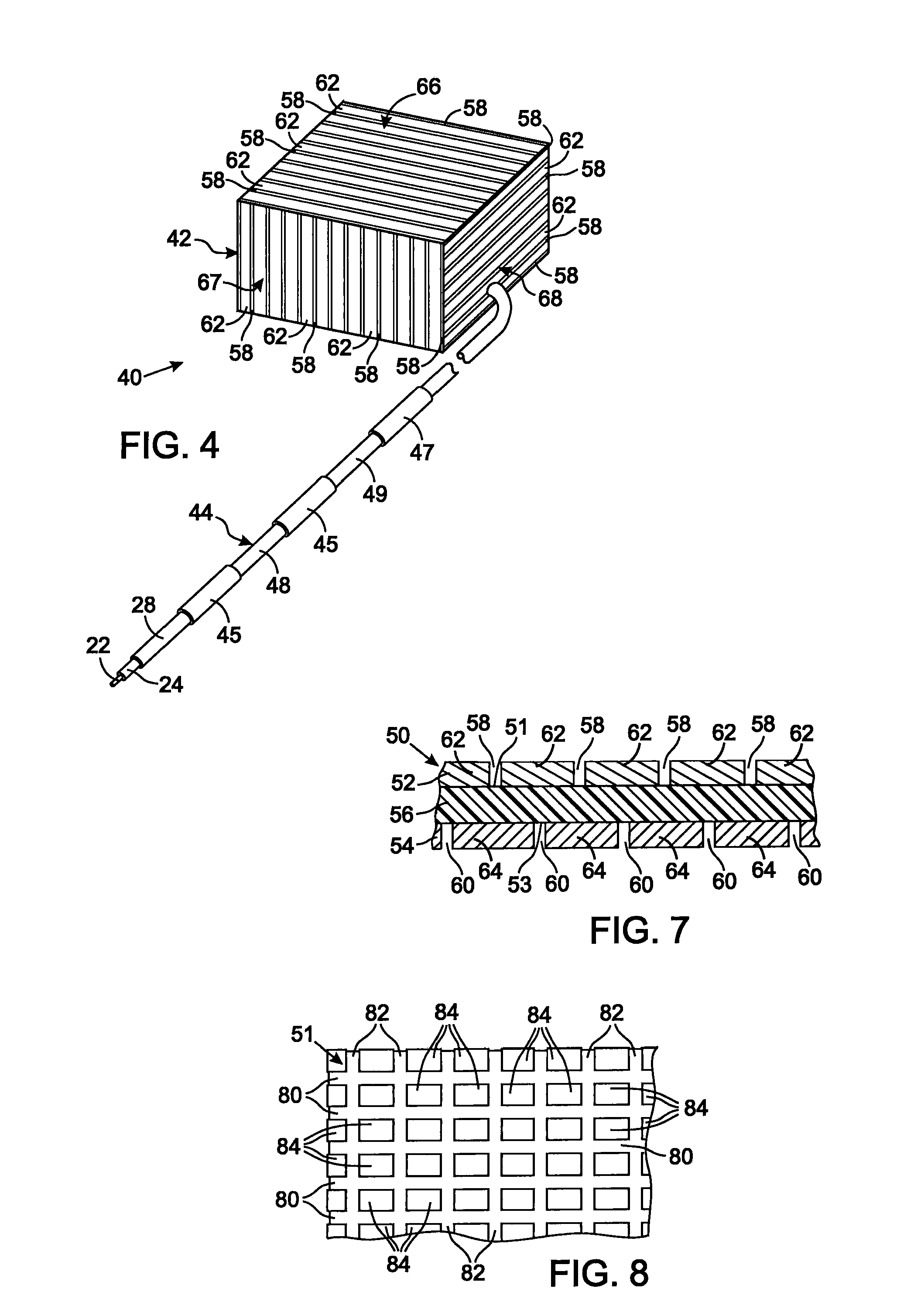
[0064]The present technique for MRI compatibility of an implanted electronic medical device considers several effects of direct current (DC) magnetic fields, gradient magnetic fields, and RF fields on patient safety, the implanted device and the MRI scanner. As a consequence, the medical device incorporates one or more mechanisms that offer high impedance to currents induced by the MRI electromagnetic fields or prevent such currents from forming in the first place. These mechanisms comprise non-ferromagnetic components which have a magnetic susceptibility close to that of the surrounding tissue; electrical leads with traps for MRI induced currents, and a housing formed by a plurality of electrically conductive segments that combine to provide RF shielding of internal circuit while not providing large enough areas for formation of eddy currents. As used herein, a “trap” is a circuit element that either blocks current induced by the MRI fields or significantly attenuates those current...


PUM


Abstract

An electrical lead, for implantation in an animal, is compatible with an MRI scanner. The electrical lead has a first plurality of coiled insulated wires forming an outer layer of conductors that has a first inductance and a first capacitance, which act as a first parallel resonator tuned to a Larmor frequency of tissue in the animal. The lead may have a second plurality of coiled insulated wires forming an inner layer of conductors within the outer layer of conductors. The second plurality of coiled insulated wires has a second inductance and a second capacitance that act as a second parallel resonator tuned to the Larmor frequency. Those parallel resonators mitigate signals at the Larmor frequency from traveling along the respective coil. An electrically conductive layer extends around the inner and / or outer layer of conductors, and a layer of a biologically compatible material forms the electrical lead's exterior surface.

Description

CROSS-REFERENCE TO RELATED APPLICATIONS[0001]This application claims benefit of U.S. Provisional Patent Application No. 61 / 142,401 filed on Jan. 5, 2009.STATEMENT REGARDING FEDERALLY SPONSORED RESEARCH OR DEVELOPMENT[0002]Not ApplicableBACKGROUND OF THE INVENTION[0003]1. Field of the Invention[0004]The present invention relates implantable electronic medical devices, such as cardiac pacemakers and defibrillators for example, for stimulating tissue of animal for the therapeutic purposes, and such implantable medical devices that are compatible with magnetic resonance imaging (MRI).[0005]2. Description of the Related Art[0006]Numerous medical conditions, such as cardiac and neurological dysfunctions, are treated by an implanted electronic device which provides electrical stimulation to the affected tissue of the animal. These devices have a plurality of metal components, including the generator case and wire leads extending from the case to electrodes in contact with the tissue to be ...

Claims


Application Information

Patent Timeline
IPC IPC(8): A61N1/05
CPCA61N1/05A61N2001/086A61N1/3718A61N1/086
Inventor BULKES, CHERIKDENKER, STEPHEN
Owner KENERGY INC
Learn More