Optical Disk Apparatus
a technology of optical disk and optical disk, which is applied in the field of optical disk apparatus, can solve the problems of difficult simultaneous pursuit for suppression of components, and achieve the effect of enhancing track follow-up performan
- Summary
- Abstract
- Description
- Claims
- Application Information
AI Technical Summary
Benefits of technology
Problems solved by technology
Method used
Image


Examples
first embodiment
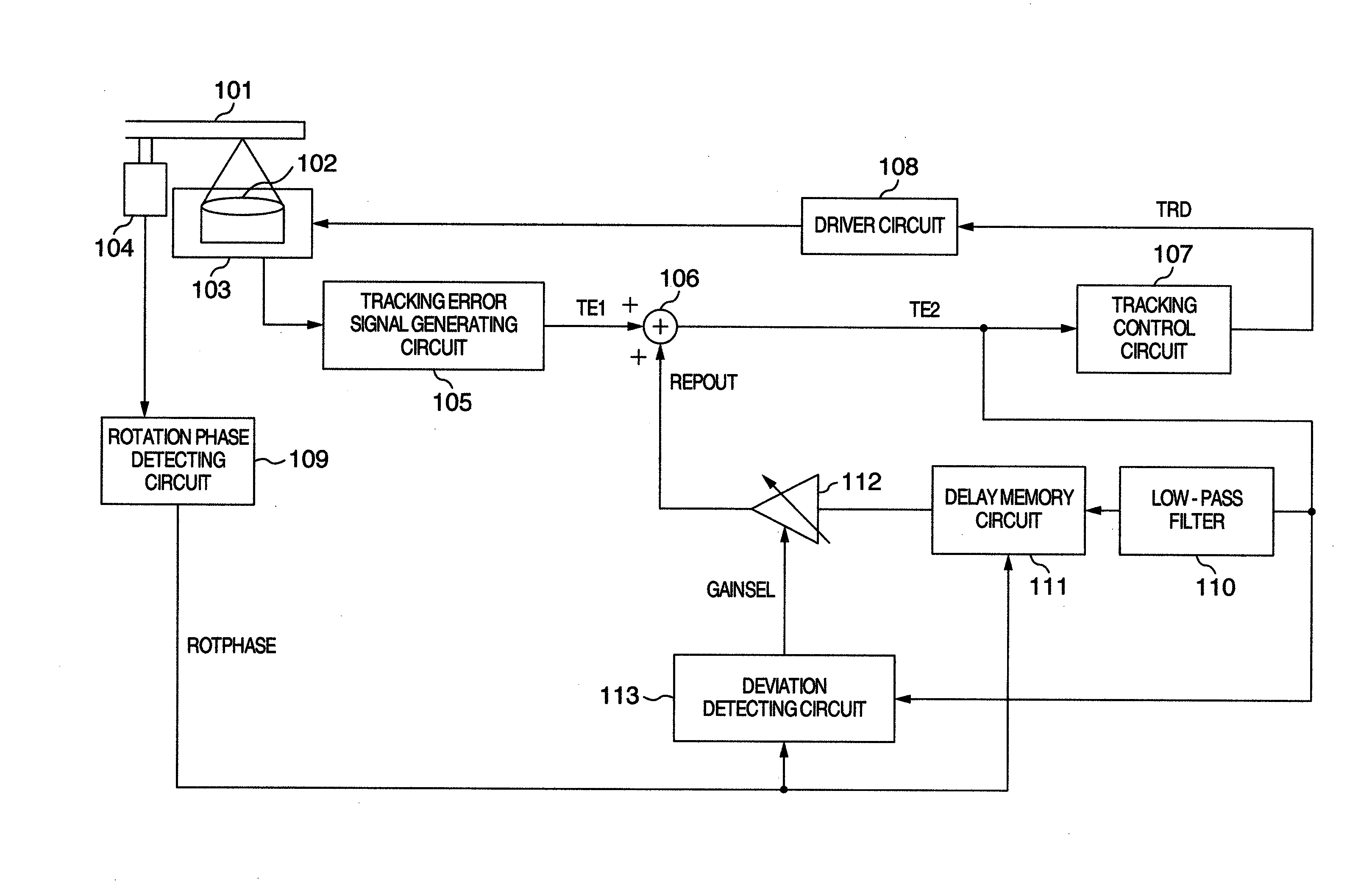
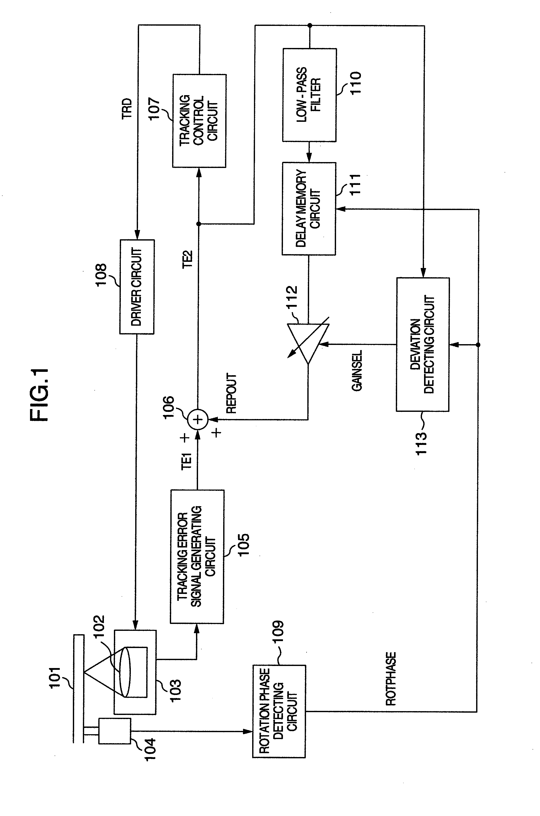
[0051]FIG. 1 is a block diagram showing an optical disk apparatus in a first embodiment.
[0052]A reference numeral 101 denotes an optical disk for reading, erasing, or writing information by irradiating a laser beam thereon.
[0053]A numeral 102 denotes an object lens which collects the laser beam to then focus it on a recording surface of the optical disk 101.
[0054]A numeral 103 denotes an optical pickup having a tracking actuator (not shown). The optical pickup 103 detects a reflected beam from the optical disk 101 to output an electric signal in response to a reflected beam amount.
[0055]A numeral 104 denotes a spindle motor which rotationally drives the optical disk 101 in a predetermined linear speed. Hereinafter, a rotation period of the spindle motor 104 is represented by Trot.
[0056]A numeral 105 denotes a tracking error signal generating circuit which generates a tracking error signal TE1 from an output signal of an optical detector in the optical pickup 103 to then output it fr...
second embodiment
[0131]A second embodiment will be described below.
[0132]The configuration of optical disk apparatus in this embodiment is common with that shown in FIG. 1.
[0133]In the first embodiment, the value of variable gain device 112 is varied in the rotation phase range indicated by the information DEVIDET. However, the server follow-up performance is possibly deteriorated at a timing when the value of variable gain device 112 is varied largely.
[0134]In the first embodiment, a variation [dB] at the time of varying the value of variable gain device 112 is represented by the following expression (3).
20Log(10.5)≈6(3)
For example, when an eccentricity component is present in the optical disk, the amplitude of compensation signal REPOUT for the eccentricity component varies twice in response to the value of variable gain device 112. Since rapidly varying the waveform of the compensation signal REPOUT causes the disturbance for the servo system, there is a possibility that the servo follow-up perfo...
third embodiment
[0145]A third embodiment in the invention will be described below.
[0146]The configuration of optical disk apparatus in this embodiment is common with that shown in FIG. 1.
[0147]The gain switching-over instruction information generating circuit 703 in the first embodiment has been configured to store the information DEVIDET of the immediately preceding one rotation amount. However, when the signal TE1 is varied by adding transiently an impact to the optical disk apparatus, the variation of signal TE1 caused by the impact is detected erroneously as a deviation, in the configuration of the first embodiment. In consequence, there is a possibility that the value of variable gain device 112 is increased.
[0148]In light of the above-mentioned problem, this embodiment is an example which does not detect erroneously the deviation when adding the impact to the optical disk.
[0149]The optical disk apparatus in this embodiment is different from that in the first embodiment in the operation of the...
PUM
| Property | Measurement | Unit |
|---|---|---|
| cutoff frequency | aaaaa | aaaaa |
| rotation frequency | aaaaa | aaaaa |
| rotation phase | aaaaa | aaaaa |
Abstract
Description
Claims
Application Information
 - R&D
- Intellectual Property
- Life Sciences
- Materials
- Tech Scout
- Unparalleled Data Quality
- Higher Quality Content
- 60% Fewer Hallucinations
Browse by: Latest US Patents, China's latest patents, Technical Efficacy Thesaurus, Application Domain, Technology Topic, Popular Technical Reports.
© 2025 PatSnap. All rights reserved.Legal|Privacy policy|Modern Slavery Act Transparency Statement|Sitemap|About US| Contact US: help@patsnap.com