
Motor driving device, motor device, and integrated circuit device

a technology of motor driving device and integrated circuit, which is applied in the direction of motor/generator/converter stopper, dynamo-electric converter control, ac motor stopper, etc., and can solve problems such as cost increas

Inactive Publication Date: 2010-07-08
PANASONIC CORP
View PDF4 Cites 11 Cited by
  • Summary
  • Abstract
  • Description
  • Claims
  • Application Information

AI Technical Summary

Benefits of technology

[0039]The motor driving device according to the present invention for driving a motor including a speed detector to detect a speed of a moving element of the motor and for outputting the speed as speed detection information, the motor driving device comprising: an inverter for converting supplied DC power to driving power to drive the motor, and for supplying the driving power to the motor; a speed control unit for generating a speed control signal group based on command information received externally and the speed detection information received from the speed detector, and for adjusting the driving power based on a drive control signal included in the speed control signal group, thereby controlling the speed of the motor; and a regeneration preventing means for determining whether the motor is in a state possibly causing regenerative phenomena or in a state not causing regenerative phenomena based on the command information and the speed detection information, and for performing a regeneration reduction process to reduce the regenerative phenomena according to the determination result, thereby preventing the regenerative phenomena.
[0040]With this structure, the period during which the motor is in a state possibly causing regenerative phenomena can be determined based on the control state of the motor, and the regenerative phenomena are kept reduced during this period, thereby preventing the occurrence of regenerative power returning to the motor driving device or the power supply device. In other words, the returning of the regenerative energy from the motor to the motor driving device or the power supply device is reduced, thereby preventing the occurrence of an overvoltage, which is due to, for example a sudden increase in the DC circuit voltage. This eliminates the need to provide in the vicinity of the motor a circuit for detecting a voltage increase due to regenerative phenomena, a circuit for detecting a voltage increase, a circuit for returning regenerative power to the power supply device, or a power supply device for absorbing regenerative power. As a result, the motor driving device has high reliability and high convenience.
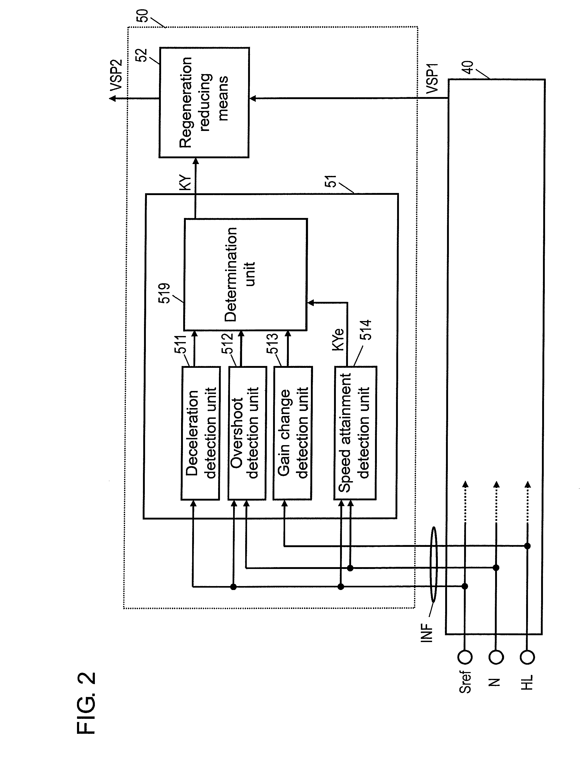
[0042]With this structure, the period after the motor enters a state possibly causing regenerative phenomena until the motor enters a state not causing regenerative phenomena is determined based on the control state of the motor. This allows the accurate determination of the period during which the motor is in a state possibly causing regenerative phenomena, so that regenerative phenomena can be kept reduced during this period, thereby preventing the returning of regenerative power to the motor driving device or the power supply device.

Problems solved by technology

On the other hand, however, the device has problems that the motor is inconvenient to use and that a larger number of peripheral circuits are required, thus leading to a cost increase.

Method used


Image

  • Motor driving device, motor device, and integrated circuit device
  • Motor driving device, motor device, and integrated circuit device
  • Motor driving device, motor device, and integrated circuit device

Examples


first exemplary embodiment

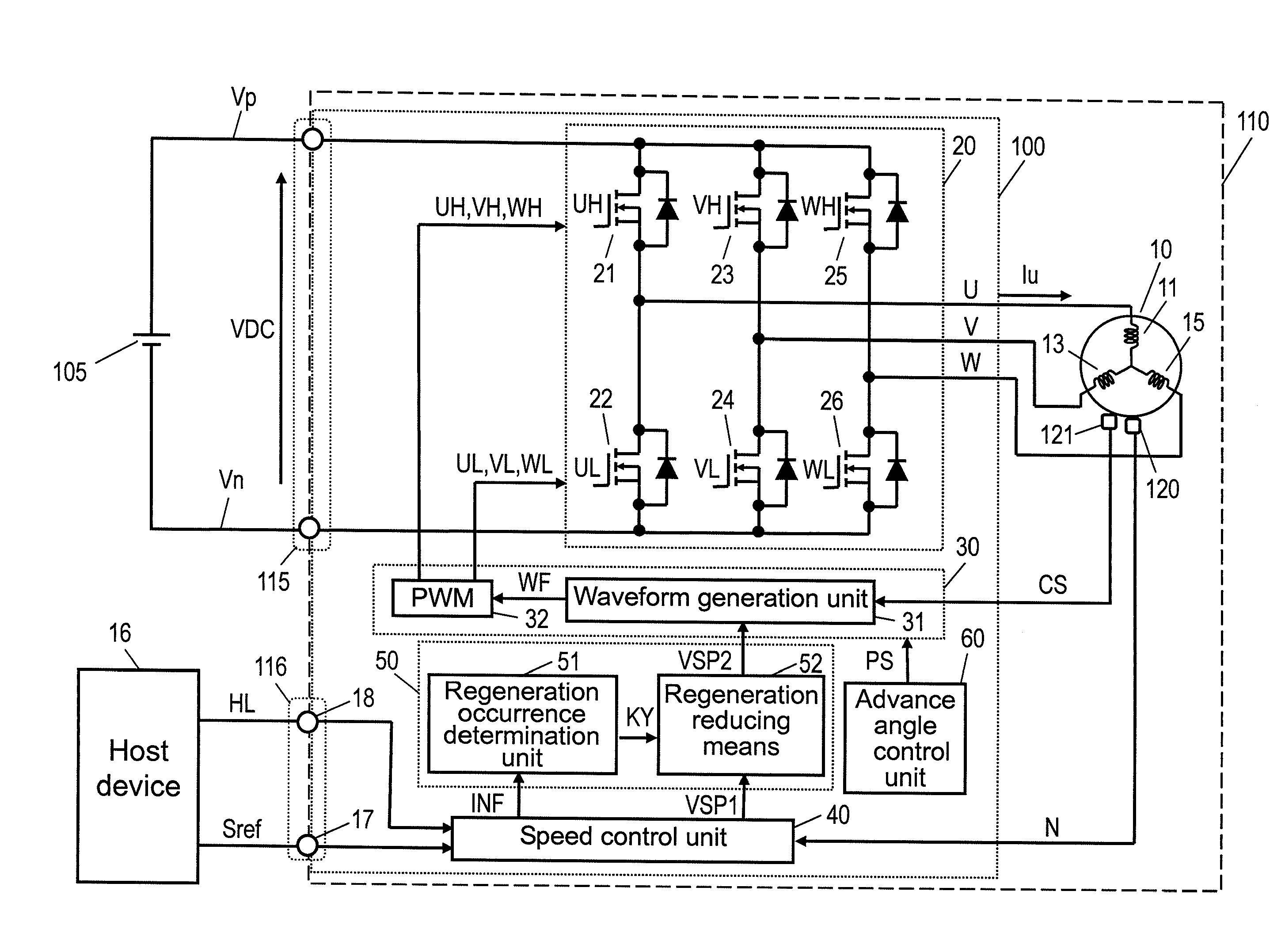
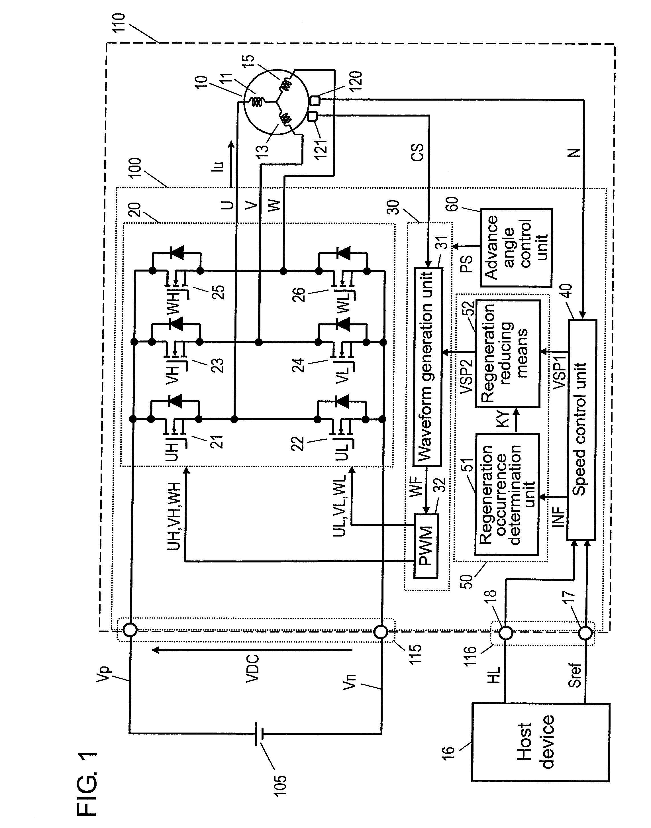
[0100]FIG. 1 is a configuration diagram showing motor device 110 including motor driving device 100 according to a first exemplary embodiment of the present invention.

[0101]As shown in FIG. 1, motor device 110 includes motor 10, speed detector 120 for detecting the speed of a moving element of motor 10, position detector 121 for detecting the position of the moving element, motor driving device 100 for driving motor 10, power input terminal 115 for receiving DC power from external DC power supply 105, and command information input terminal 116 for receiving command information from external host device 16.

[0102]Host device 16, which can be provided in a device having motor device 110, is composed of a microcomputer, a DSP, or the like. Host device 16 sends command information for commanding and controlling the speed of motor device 110 to motor device 110. In the present exemplary embodiment, as the command information, a speed command signal Sref and a switching signal HL are input...

second exemplary embodiment

[0173]FIG. 7 is a configuration diagram showing motor device 110 including motor driving device 100 according to a second exemplary embodiment of the present invention.

[0174]Unlike motor driving device 100 according to the first exemplary embodiment shown in FIG. 1, in motor driving device 100 according to the second exemplary embodiment, inverter drive unit 30 includes pulse-width modulation unit 232, which also functions as a regeneration reducing means in the regeneration preventing means. As described in the conventional art, regenerative phenomena occur when switch elements 21 and 22 and the other switch elements composing inverter 20 are turned on and off complementarily. Therefore, regenerative phenomena can be prevented by turning one switch element on and off while the other switch element is in the OFF state, instead of turning both switch elements on and off complementarily.

[0175]More specifically, in motor driving device 100 of the present exemplary embodiment, pulse-wid...


PUM


Abstract

A motor driving device (100) includes an inverter (20), a speed control unit (40), and a regeneration preventing means (50). The inverter (20) converts supplied DC power to driving power for driving a motor (10), and supplies the driving power to the motor (10). The speed control unit (40) generates a speed control signal group based on a speed command signal Sref and a speed detection signal N, and adjusts the driving power based on a drive control signal VSP1 included in the speed control signal group, thereby controlling the speed of the motor (10). The regeneration preventing means (50) determines whether the motor (10) is in a state possibly causing regenerative phenomena or in a state not causing regenerative phenomena based on the speed command information included in the speed command signal Sref and the speed detection information included in the speed detection signal N, and performs a regeneration reduction process to reduce regenerative phenomena according to the determination result, thereby preventing regenerative phenomena.

Description

TECHNICAL FIELD[0001]The present invention relates to a motor driving device suitable for driving, for example, a brushless DC motor used in air conditioners, water heaters with a combustion fan motor, air cleaners, information devices such as copying machines and printers, and other similar devices. The present invention relates, more particularly, to a motor driving device capable of reducing regenerative phenomena when the motor is sine- wave driven, allowing the motor to be driven with substantially low levels of torque ripple, vibration, and noise. The present invention also relates to an integrated circuit device including such a motor driving device, and a motor device in which such a motor driving device or an integrated circuit device is built-in or integrated with a motor.BACKGROUND ART[0002]Most driving motors used in electrical devices such as air conditioners, water heaters, air cleaners, copying machines, and printers are brushless DC motors because they have advantage...

Claims


Application Information

Patent Timeline
Patent Type & Authority Applications(United States)
IPC IPC(8): H02H7/08
CPCH02P3/18H02P23/06H02P6/12H02P27/06
Inventor YASOHARA, MASAHIROSUGIURA, KENJI
Owner PANASONIC CORP
Learn More