
Bit mapping/demapping method and apparatus for communication system

a communication system and bit mapping technology, applied in the field of communication systems, can solve the problems of not maximizing the benefit of ldpc codes, failing to minimize the distortion of transmission signals, and likely distortion of signals transmitted over air, and achieve the effect of improving the coding gain of ldpc codes

Inactive Publication Date: 2010-06-24
SAMSUNG ELECTRONICS CO LTD
View PDF4 Cites 20 Cited by
  • Summary
  • Abstract
  • Description
  • Claims
  • Application Information

AI Technical Summary

Benefits of technology

[0033]In order to solve at least the above mentioned problems, the present invention provides a symbol mapping method and apparatus for a communication system using LDPC codes that is capable of improving the coding gain of the LDPC codes.
[0034]Also, the present invention provides a symbol demapping method and apparatus for a communication system using LDPC codes that is capable of improving system throughput.

Problems solved by technology

Typically, the signal transmitted over the air is likely to be distorted by noise and fading effects of the channel and Inter-Symbol Interference (ISI).
Particularly in the high speed digital communication systems (such as next generation mobile communication systems, digital broadcast systems, broadband Internet access systems), overcoming these noise, fading, and ISI problems is one of the significant issues to fulfill the high data rate and reliability requirements.
Soon after the invention of the LDPC codes, they were forgotten due to their implementation complexity that surpassed the technology at that time.
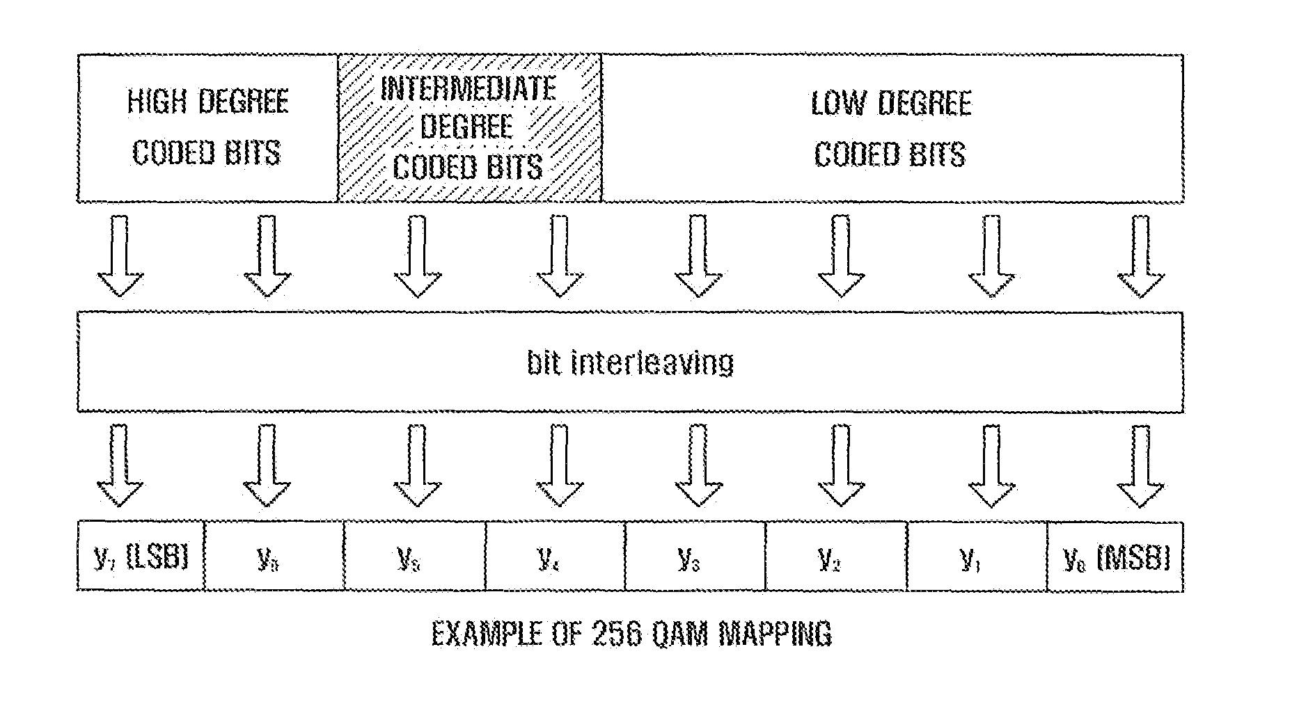
In the conventional communication systems based on LDPC codes, however, interleaving and deinterleaving is performed without taking into consideration the characteristics of the reliabilities of the bits constituting the LDPC code or high order modulated codes, or only taking into consideration the order of variable nodes or check nodes, thereby failing to minimize the distortion of the transmission signal.
Furthermore, the conventional LDPC code-based communication systems are implemented in a group of two consecutive bits, y2i and y2i+1, only with the reason that these two bits are identical to each other in reliability, thereby failing to maximize the benefit of LDPC codes.

Method used


Image

  • Bit mapping/demapping method and apparatus for communication system
  • Bit mapping/demapping method and apparatus for communication system
  • Bit mapping/demapping method and apparatus for communication system

Examples


Embodiment Construction

[0054]Embodiments of the present invention are described in detail with reference to the accompanying drawings. The same reference numbers are used throughout the drawings to refer to the same or like parts. Detailed descriptions of well-known functions and structures incorporated herein may be omitted to avoid obscuring the subject matter of the present invention.

[0055]The terms and words used in the following description and claims are not limited to the bibliographical meanings, but are merely used to enable a clear and consistent understanding of the invention. Accordingly, it should be apparent to those skilled in the art that the following description of embodiments of the present invention are provided for illustration purpose only and not for the purpose of limiting the invention as defined by the appended claims and their equivalents.

[0056]FIG. 4 is a block diagram illustrating configurations of a transmitter and a receiver of a communication system using LDPC code accordin...


PUM


Abstract

An improved bit mapping method and apparatus for a communication system is provided. A bit mapping method of the present invention includes arranging coded bits in a codeword in an order of recovery capability; setting a shift region including a number of coded bits; rearranging the coded bits in the shift region by shifting the shift region by a number of bits equal to a number of bits that is indicated by a shift factor; and mapping the rearranged coded bits into a modulation symbol in an order of reliability from a lowest reliability bit position to a highest reliability bit position of the modulation symbol.

Description

PRIORITY[0001]This application claims priority to an application entitled “BIT MAPPING / DEMAPPING METHOD AND APPARATUS FOR COMMUNICATION SYSTEM” filed in the Korean Intellectual Property Office on Dec. 18, 2008 and assigned Serial No. 10-2008-0128938, the contents of which are hereby incorporated by reference.BACKGROUND OF THE INVENTION[0002]1. Field of the Invention[0003]The present invention relates generally to a communication system and, in particular, to an improved bit mapping method and apparatus for a communication system.[0004]2. Description of the Related Art[0005]In a wireless communication system, the data generated at a source is transmitted after being subject to signal processing, which may include source coding, channel coding, interleaving, modulation, and further suitable steps. The signal received at a destination is subject to signal processing, which may include demodulation, deinterleaving, channel decoding, and source decoding, and further suitable steps.[0006]...

Claims


Application Information

Patent Timeline
Patent Type & Authority Applications(United States)
IPC IPC(8): H03M13/05G06F11/10
CPCH03M13/1102H03M13/255H03M13/356H03M13/616H04L1/0057H04L27/34H04L2001/0098H03M13/11
Inventor MYUNG, SE HOKIM, JAE YOELLIM, YEON JUYUN, SUNG RYULLEE, HAK JU
Owner SAMSUNG ELECTRONICS CO LTD
Learn More