Device and Method for Manipulating and Mixing Magnetic Particles in a Liquid Medium

Inactive Publication Date: 2010-06-24
SPINOMIX
View PDF19 Cites 18 Cited by
  • Summary
  • Abstract
  • Description
  • Claims
  • Application Information

AI Technical Summary

Benefits of technology

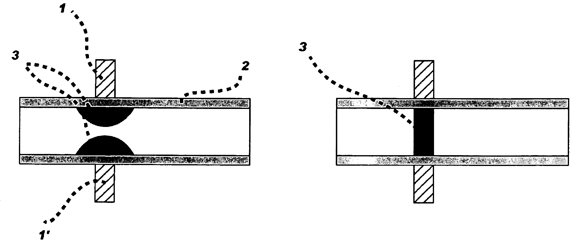
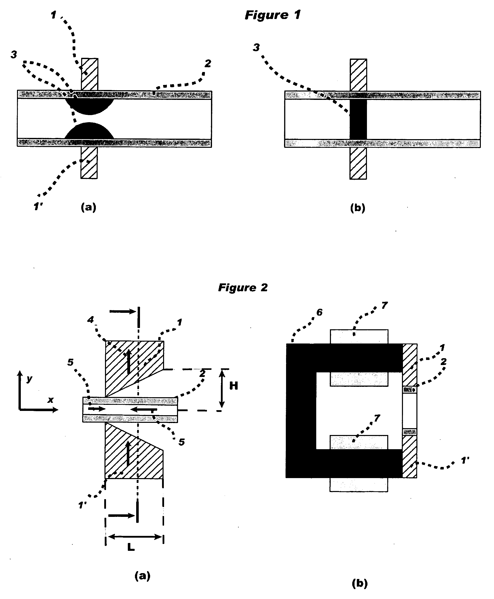
[0065]To illustrate the key advantage of the present invention, FIG. 1 schematically shows the concept of a flow-through magnetic particles handling approach as described in the prior art. In the prior art indeed, the particles (3) are kept fixed in a narrow region of a flow-through cell (2) delimited by magnetic pole tips (1) and (1′). The particles can partially cover the flow-through cell cross section (FIG. 1 (a)) when a static field is applied as described in U.S. patent application 2004 / 166,547, or homogenously cover the flow cell cross section (FIG. 1 (b)) when a time varied magnetic field is applied as described in U.S. patent application 2005 / 208,464. The pole tip configurations used to generate a magnetic field gradient confine the particles in a stationary fixed and narrow segment of the flow-through cell, which limits the contact between the particles and the target molecules to that narrow region and for a very short time.

Problems solved by technology

Indeed, as for any surface-based assay the reaction is strongly limited by the natural diffusion process, a strong steering and mixing is necessary to promote the affinity binding reaction between the ligand and the target substance.
However, with this method the magnetic field gradient will attract and confine the particles in a cavity region close to the walls of the container.
In such condition, the contact between the particles and the test medium is limited to the said cavity space which reduces the mixing efficiency.
In such conditions indeed, the particles can be moved while relatively separated from each other, which will potentially affect the mixing.
However, in this approach when one takes in consideration the whole duration of the particles handling process, the time during which the particles are relatively separated from each other is relatively short.
Moreover, during the mixing process the particles are not homogenously contacted with the sample volume in the test tube, which will in turn strongly limit the mixing efficiency.
This issue is more pronounced as the sample volume is large.
Consequently when these mechanical mixing approaches are compared with the “manual shaking of a test tube”, the reaction time and the performance are substantially similar if not lower, indicating that diffusion is still an important limiting factor.
This process limits the movement of the particles to a relatively small distance, significantly reducing the mixing efficiency between particles and the surrounding liquid medium.
In general, beyond the limited mixing capability of the state of the art magnetic particles technologies, mainly based on the concept of “bringing a magnet in the proximity of a test tube”, the integration and the automation of magnetic particles assay procedures are very complex, necessitating bulky robotic systems.
These limitations become all the more critical as the assay procedures are becoming more and more complex.
The major limitation of this “in flow mixing” approach is that the volume of the test medium that can be mixed with the particles is very small and the reaction time very short, limiting considerably the cases of its applicability.
However the so described flow-through approach suffers from a serious physical constraint, since in order to be handled in an environment with continuous fluidic processing, the particles must be continuously exposed to a magnetic field.
Under such conditions the particles will stick together and agglomerate thereby losing their main advantage: the particle surface that is in active contact with the fluid flow will be drastically reduced which will seriously compromise the assay performance.
Even demonstrating an important development in magnetic particles handling and mixing in a microfluidic environment, the approach disclosed in U.S. patent application 2005 / 208,464 suffers however from many practical limiting constraints.
First, as the particles are kept stationary and fixed in a narrow segment of the flow-through cell, the contact between the particles and the target substance is limited to that narrow region and for a very short time, which in practice makes such process difficult to set up.
Secondly, this approach is specifically adapted for handling and mixing magnetic particles under flow-through conditions in microfluidics environments, which make it not fully adapted for different assay conditions.

Method used


Image

  • Device and Method for Manipulating and Mixing Magnetic Particles in a Liquid Medium
  • Device and Method for Manipulating and Mixing Magnetic Particles in a Liquid Medium
  • Device and Method for Manipulating and Mixing Magnetic Particles in a Liquid Medium

Examples


example 1

of Actuation Mechanism

[0110]The actuation sequences of FIG. 7, is an illustration on how the magnetic particles, while the magnetic poles are actuated using a time varied (amplitude and polarity) magnetic field, is used as a base sequence, can be moved following the combination of the magnetic field from each magnetic pole. During this movement the particles will substantially cover the whole reaction chamber volume as a fog of particles thereby assuring mixing. Although represented as “discontinuous” sequences, the sequences of the particles as shown in FIG. 7 can be achieved with a “rotating magnetic field” following the magnetic poles actuation sequences:

Pole 1 and 10′: B=B0 sin(ft)

Pole 1′ and 10: B=B0 sin(ft+π / 2)  (3)

[0111]In equation (3) the base sequence actuation in each magnetic pole is an oscillating field while the actuation process is assured by a phase shift of π / 2 between the diagonally coupled magnetic poles. In this configuration the base and the sequence actuation fi...

example 2

of Actuation Mechanism

[0117]Equation (4) describes another actuation sequences to achieve mixing according to the invention.

Pole 1 and 10′: B=B0 sin(f1t)sin(f2t)

Pole 1′ and 10: B=B0 sin(f1t)sin(f2t+π / 2)  (4)

[0118]In this sequence indeed the first oscillation component (sin(f1t)) is nothing more than the base actuation field at a frequency f1 of the magnetic poles while the second term defines the actuation sequence that moves the “fog” of particles in rotation form with a frequency f2. The sequence of equation (4) allows in particular to solve the previously reported (in the Example 1) agglomeration of particles in a low frequency rotating field of equation (3). For instance by rotating the particles as a frequency f2=1 Hz, the particles chains will break down due to the fast oscillation of the base field f1>10 Hz.

[0119]Example 3 of Actuation Mechanism

[0120]Equation (5) describes another actuation sequence to achieve mixing according to the invention, where the frequency of the rota...

example 4

of Actuation Mechanism

[0124]Although the previous examples are based on using “rotating magnetic field”, linear actuation sequence of particles fog can be also used to mix and reach an homogenous state. Typical example of that linear actuation mode can be achieved by first moving the particles to the out border as shown in FIG. 7(b) using the actuation sequence:

Pole 1 and 1′: B=B0 sin(ωt)

Pole 10 and 10′: B=B0 sin(ωt+π)  (6)

[0125]At this stage the particles can be moved to the left corner (narrow part) of the reaction chamber by the sequence:

Pole 1 and 1′: B=B0 sin(ωt)

Pole 10 and 10′: B=B0 sin(ωt+ / 2)  (7)

[0126]By symmetry a displacement toward the right corner (narrow part) of the reaction chamber can be achieved by the sequence:

Pole 1 and 1′: B=B0 sin(ωt+π / 2)

Pole 10 and 10′: B=B0 sin(ωt)  (8)

[0127]A sequential shift between the previous three configuration following the sequences: (6)→(7)→(6)→(8) at a determined rate, one can achieve an homogenous mixing over the time.

[0128]In pract...


PUM


Abstract

A device for manipulating and mixing magnetic particles (3) in a surrounding liquid medium, comprises at least one couple of magnetic poles (1,1′) facing each other across a gap, the facing poles diverging from a narrow end of the gap to a large end of the gap, the poles (1,1′) forming part of an electromagnetic circuit and being arranged to provide a magnetic field gradient in the gap region; and a reaction chamber (2) that is a part of a fluidic network for containing the said magnetic particles in suspension and placed in the gap of the said electromagnets poles (1,1′). The reaction chamber (2) preferably has at least one part which has a diverging cavity, arranged co-divergently in the diverging gap between the poles.

Description

REFERENCE TO RELATED APPLICATIONS[0001]This application claims benefit of International Application No. PCT / IB2007 / 052409 filed on 21 Jun. 2007, International Application No. PCT / IB2007 / 052410 filed on 21 Jun. 2007, International Application No. PCT / IB2006 / 052005 filed on 21 Jun. 2006, and International Application No. PCT / IB2006 / 054182 filed on 9 Nov. 2006, which are incorporated by reference herein.FIELD OF THE INVENTION[0002]The invention relates to a system of handling and mixing magnetic particles within a reaction chamber that is a part of a fluidic or microfluidic platform. More particularly, the invention concerns a method of handling magnetic particles in a way to improve the mixing of the particles with the surrounding liquids medium and where the liquids are automatically handled in a fluidic platform. Further, the invention relates to a method for conducting assays on a test sample containing specific biological or chemical substances using active biochemically surface m...

Claims


Application Information

Patent Timeline
IPC IPC(8): B01F13/08
CPCB01F13/0809C12N15/1013G01N1/38G01N35/0098B01F33/451
Inventor RIDA, AMAR
Owner SPINOMIX
Why Eureka
Try Eureka