Restraining gasket for mechanical joints of pipes
- Summary
- Abstract
- Description
- Claims
- Application Information
AI Technical Summary
Benefits of technology
Problems solved by technology
Method used
Image
Examples
Embodiment Construction
[0028] The following is a detailed description of the invention. Those skilled in the art will understand that the specificity provided herein is intended for illustrative purposes with respect to the inventor's most preferred embodiment, and is not to be interpreted as limiting the scope of the invention. References to “pipe” herein shall be understood equally to refer to any pipe length, appurtenance, fitting, or any other connected device or element.
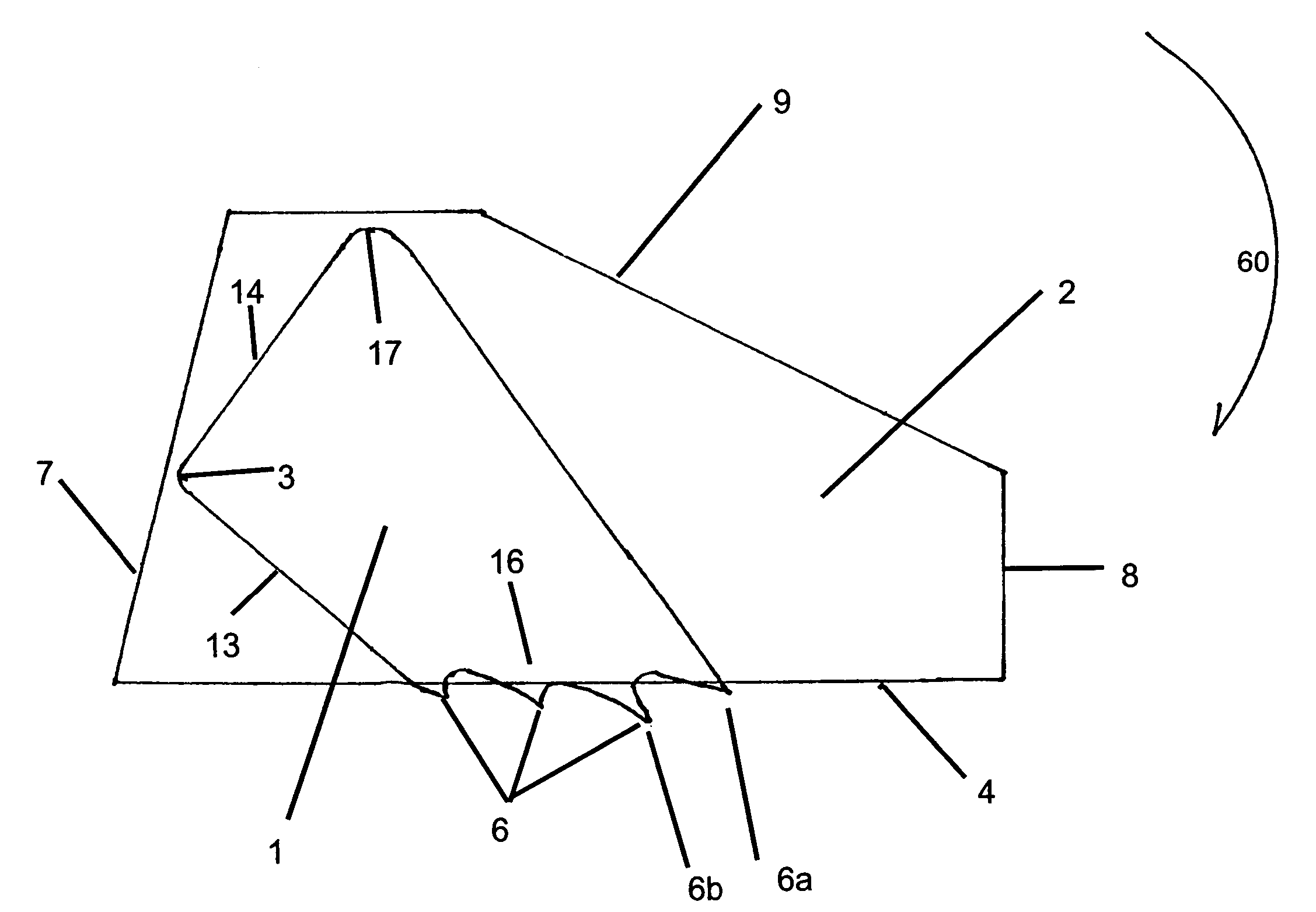
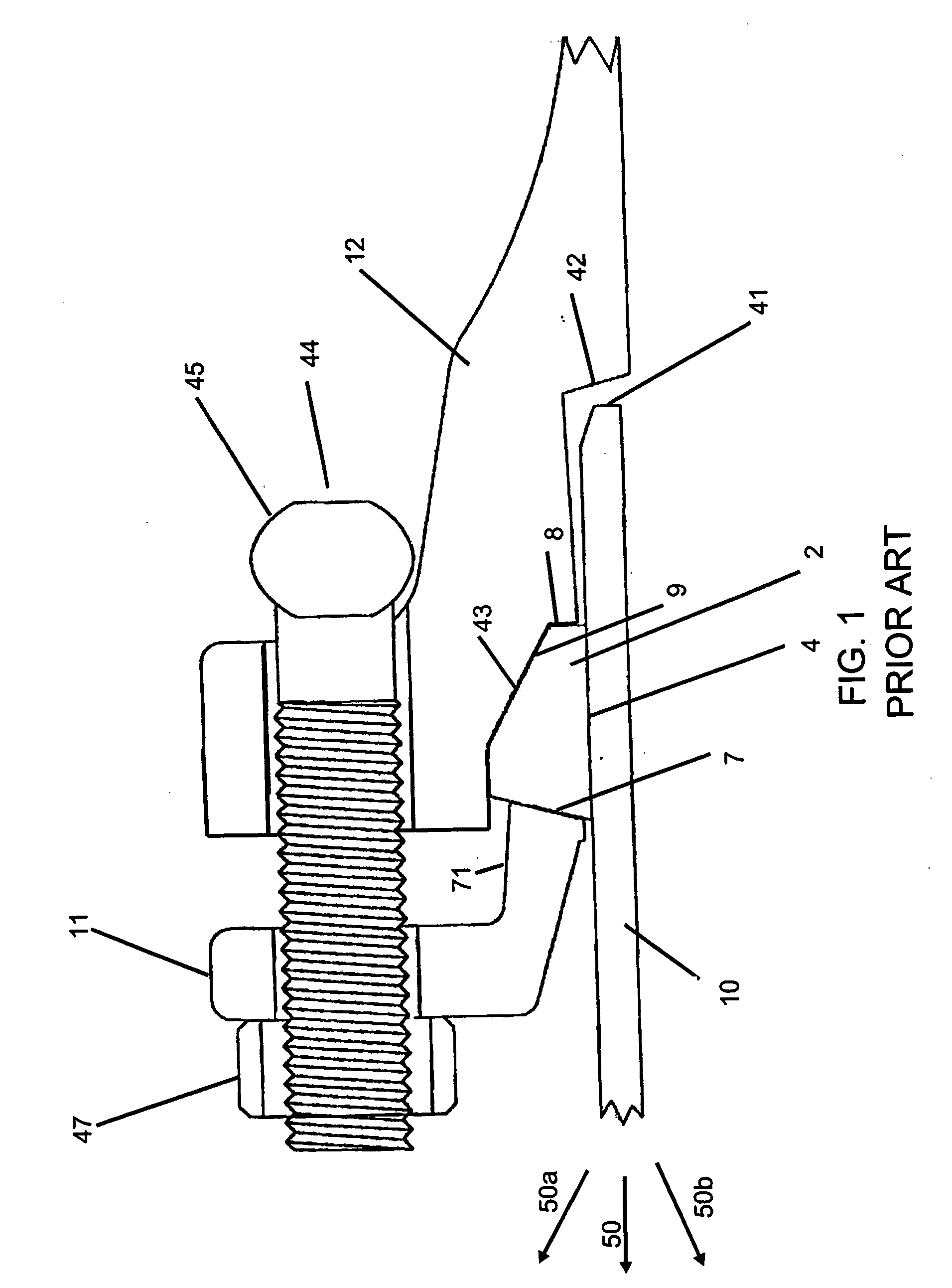
[0029] Turning now to the drawings, FIG. 1 presents an exploded diagram of a typical mechanical joint. Assembly of the joint according to the current invention is practiced as known in the art. Particularly, without limitation of the known variants which shall be as equally applicable to the present invention as they are to the known art, the joint contains the following elements in the following relationship. Compression ring or gland 11 is placed on spigot 10, following which gasket 2 is placed around the exterior of spigot 10. Spi...
PUM
 Abstract
Description
Claims
Application Information
 - R&D
- Intellectual Property
- Life Sciences
- Materials
- Tech Scout
- Unparalleled Data Quality
- Higher Quality Content
- 60% Fewer Hallucinations
Browse by: Latest US Patents, China's latest patents, Technical Efficacy Thesaurus, Application Domain, Technology Topic, Popular Technical Reports.
© 2025 PatSnap. All rights reserved.Legal|Privacy policy|Modern Slavery Act Transparency Statement|Sitemap|About US| Contact US: help@patsnap.com


