
Compressible Photonic Crystal

a photonic crystal and compressible technology, applied in the field of compressible photonic crystals, can solve the problems of affecting the application of the structure, affecting the stability of the longer-term, and not being suitable for many applications, so as to reduce the redistribution of stress, improve the stability of use, and be more homogeneous in the behaviour

Active Publication Date: 2010-06-17
THE GOVERNINIG COUNCIL OF THE UNIV OF TORANTO +1
View PDF10 Cites 81 Cited by
  • Summary
  • Abstract
  • Description
  • Claims
  • Application Information

AI Technical Summary

Benefits of technology

[0014]In the case where the lattice structure is modulated, a particularly desirable attribute is elasticity of the PC, resulting in reversible tuning. This means the PC may be deformed in response to an external stimulus, then allowed to completely or partially recover, and may be cycled repeatedly.
[0020]Porous polymer PCs can be compressed with minimal change in structural dimension in directions other than the direction of compression, reducing the redistribution of stress along lateral directions when compressed by a patterned surface. That is, aside from the compressed surface, the uncompressed surfaces of the PC do not expand or bulge out, or otherwise significantly deform or distort. There is no significant change in the lateral dimensions. This results in a PC that exhibits more homogenous behaviour and is more stable in use.

Problems solved by technology

The photonic crystal disclosed in this reference is in block form, which may not be suitable in many applications.
The hydrogel PC is compressible, but the fragility of its structure hinders its application.
Since PC devices are fashioned as a film on a substrate, lateral expansion is accompanied by delamination from the substrate, inhomogeneity in color shift, and / or unrelieved stress in the material leading to loss of longer-term stability.

Method used


Image

  • Compressible Photonic Crystal
  • Compressible Photonic Crystal
  • Compressible Photonic Crystal

Examples


example 1

[0052]One example of the present invention is a substantially reversible elastic PC (EPC), in which the photonic crystal comprises alkylmethacrylate as the polymer, with an ordered array of voids.

[0053]In this example, the EPC has an area of 1 cm2 and a thickness of about 5 micrometers. The EPC rests on a glass substrate, although any material can be used for the substrate. A thicker, more rigid EPC can be used without a substrate. However, a soft EPC is preferred for better responsiveness.

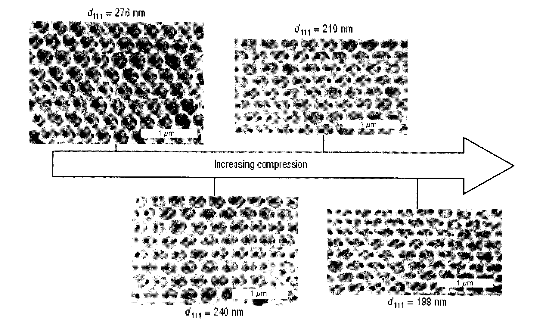
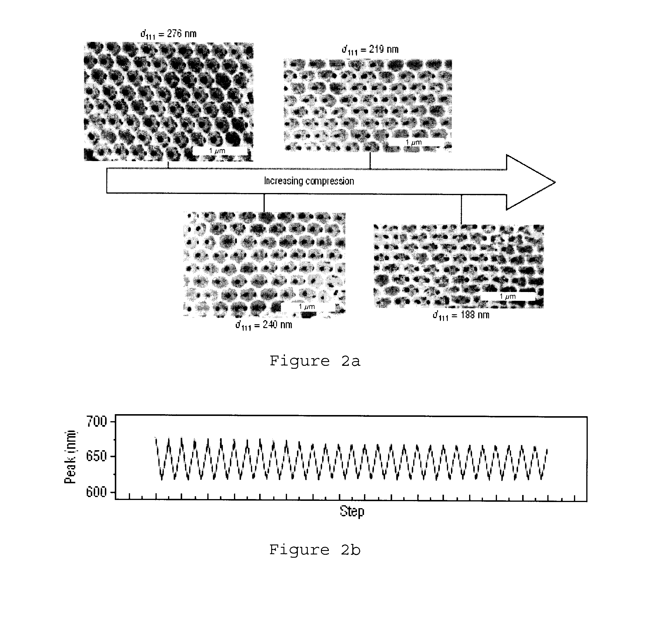
[0054]FIG. 2a shows the distortion of the voids upon vertical compression. The images shown in FIG. 2a were taken using scanning electron microscope (SEM). SEM measurements were performed on a Hitachi S-5200 SEM, using an accelerating voltage of 1.5 kV and arc-coating the samples with a thin carbon film before imaging. The monomer composition of the imaged samples was a methyl methacrylate-butyl methacrylate mixture, which is glassy at room temperature. The EPC was heated to between 60° C. and 120...

example 2

[0056]FIG. 2b shows the compression-decompression cycling of the reflectance peak position for an EPC with about 350 nm diameter voids, subjected to a spring-coupled actuator compression of 12 mm resulting in approximately 15 kPa compressive stress. Spectra were collected at 1.2 mm compression intervals.

example 3

[0057]FIGS. 2c and 2d show the reflectivity spectra of normal incident light during compression of EPCs with 350 nm and 710 nm diameter voids, respectively. The spectra can be seen to blueshift (i.e. shift to shorter wavelengths) during compression. Note that the amount of blueshift is dependent on the amount of compression applied.

Manufacture of Photonic Crystal

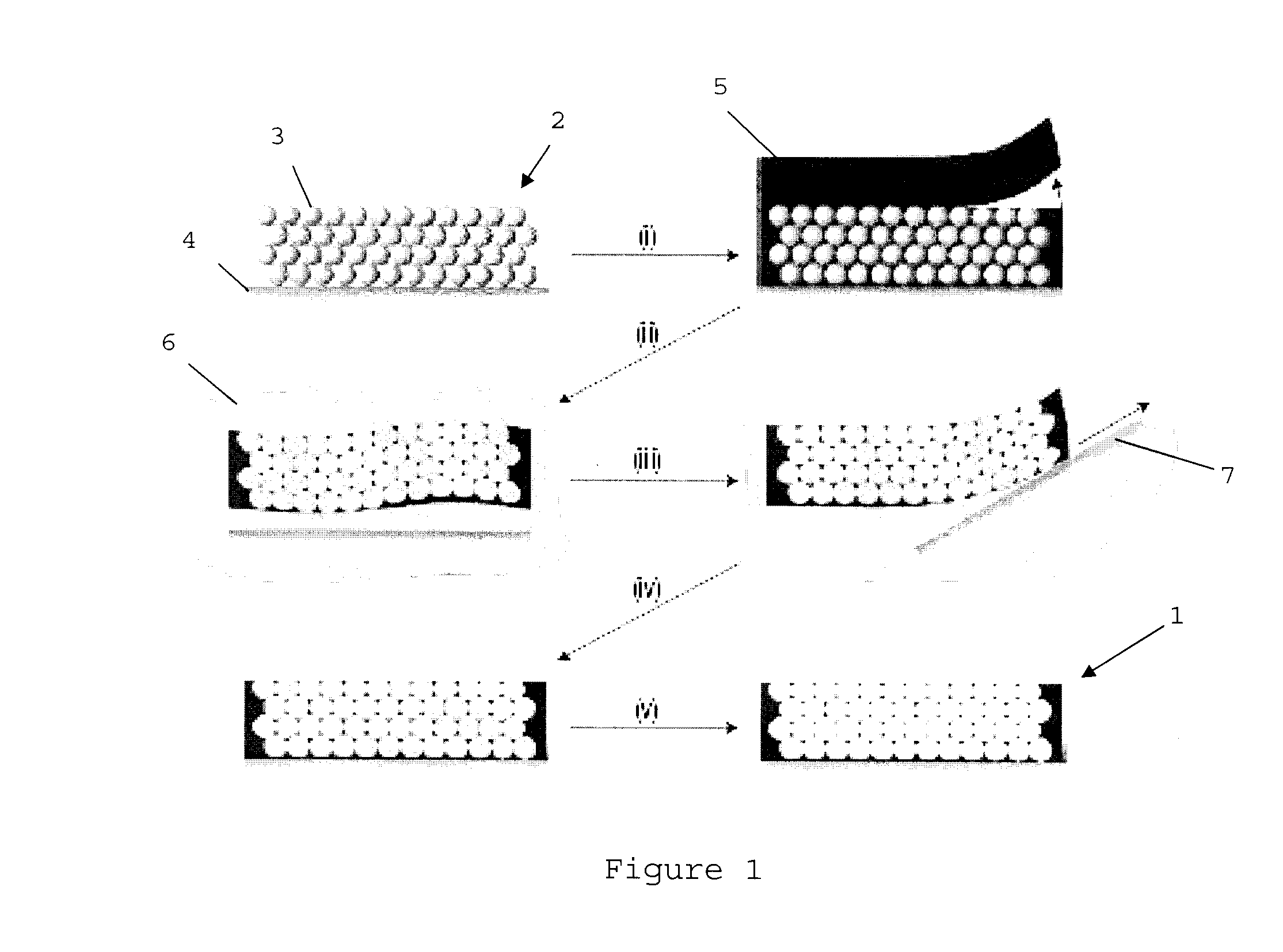
[0058]One aspect of the present invention is a method of manufacturing a compressible photonic crystal, preferably as a film, as illustrated in FIG. 1 and described below.

[0059]One preferred embodiment of the manufacturing method is a templating strategy to fabricate the PC 1, which provides control over both the material composition and structural order. The method is illustrated in FIG. 1 and has the following steps (all compounds mentioned below are standard compounds available from sources such as Sigma-Aldrich):

[0060](i) Formation of the microsphere template film 2, preferably using a colloidal PC film of high-quality s...


PUM

PropertyMeasurementUnit
thicknessaaaaaaaaaa
diameteraaaaaaaaaa
diameteraaaaaaaaaa

Abstract

A compressible photonic crystal comprising a polymer with an ordered array of voids, the photonic crystal having a reflectance in a first wavelength range for light incident to its incident surface and its opposing incident surface; wherein compression against at least a portion of at least one of the surfaces shifts the reflectance to a second wavelength range in at least that portion of that surface. The crystal may be used in authentication devices of various types.

Description

FIELD OF THE INVENTION[0001]The invention relates to a compressible photonic crystal.BACKGROUND OF THE INVENTION[0002]Photonic crystals (PCs) are materials having a periodic modulation in their refractive index (Yablonovitch, Phys. Rev. Lett., 58:2059, 1987), giving rise to a photonic band gap or stop gap, in which electromagnetic waves within a certain stop band wavelength range are totally reflected. The wavelengths of the stop band are dependent on the distance between the periodic modulations in the crystal. The reflected stop band wavelengths appear in the reflectance spectrum as a distinct reflectance peak known as a Bragg peak. The crystal may have a one-, two-, or three-dimensional periodic structure.[0003]Because of the sensitivity of a PC, slight changes in the refractive index or lattice spacing results in detectable changes in the reflected light. This is particularly useful where the reflected light is in the visible range, allowing for sensors with a colour-based respo...

Claims


Application Information

Patent Timeline
Patent Type & Authority Applications(United States)
IPC IPC(8): G02F1/01C08F20/10C08F20/26C08L33/12C08L33/14C08F2/46
CPCB82Y20/00G02B6/1225C08J5/18
Inventor ARSENAULT, ANDREOZIN, GEOFFREY ALANVON FREYMANN, GEORG
Owner THE GOVERNINIG COUNCIL OF THE UNIV OF TORANTO
Learn More