Webbing retracting device
a retracting device and webbing technology, applied in the direction of belt retractors, vehicle safety belts, vehicle components, etc., can solve the problems of difficult pulling out of webbing belts, the shaft of reels cannot rotate in the pull out direction,
- Summary
- Abstract
- Description
- Claims
- Application Information
AI Technical Summary
Benefits of technology
Problems solved by technology
Method used
Image
Examples
first exemplary embodiment
Configuration of the First Exemplary Embodiment
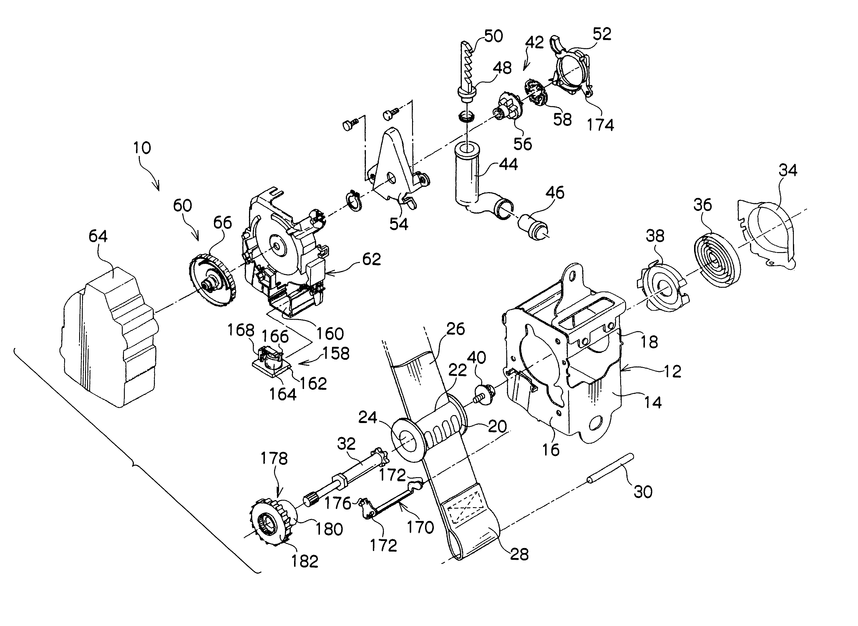
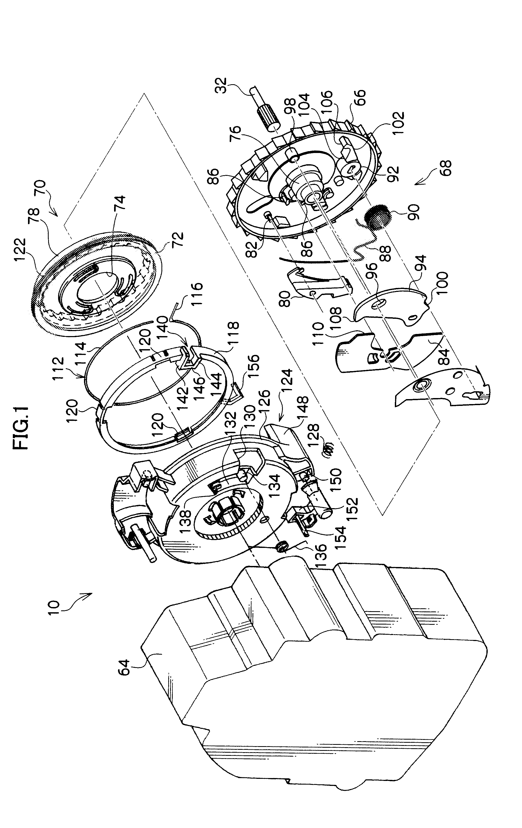
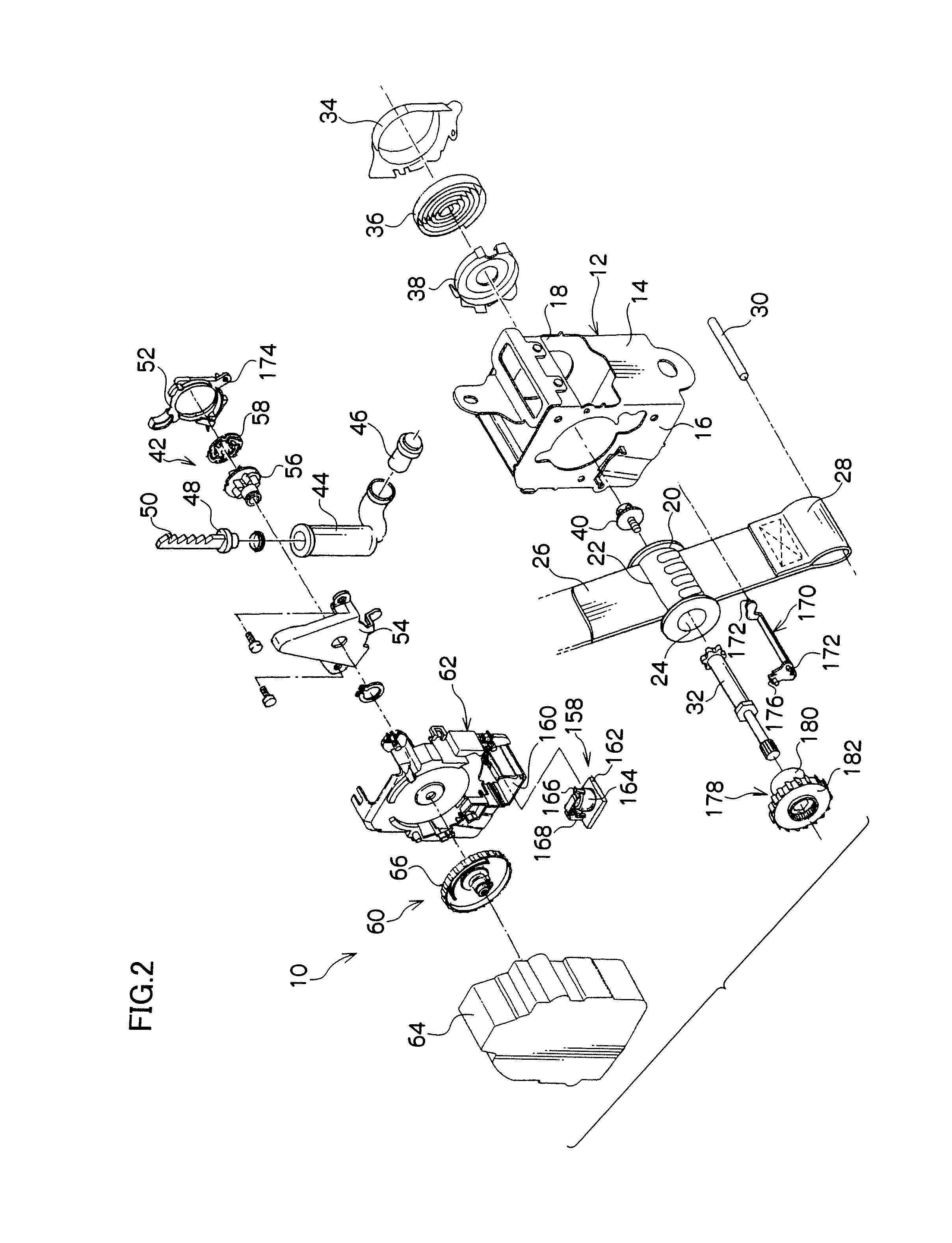
[0057]In FIG. 2 the overall outline configuration of a webbing retracting device according to a first exemplary embodiment of the present invention is shown through an exploded perspective view.
[0058]As is shown in the figure, a webbing retracting device 10 is provided with a frame 12. The frame 12 is, for example, provided with a back plate 14 that is a plate shape with a thickness direction thereof that is in the substantially left-right direction of a vehicle. The present webbing retracting device 10 is a structure that is attached to a vehicle body, by the back plate 14 being fixed with fasteners, such as bolts or the like, for example, to a vehicle body in the vicinity of a lower end of a center pillar. A leg plate 16 is formed from one width direction side of the substantially vehicle front-rear direction back plate 14, bent around toward the inside in the width direction of the vehicle (substantially the vehicle left-right direct...
second exemplary embodiment
Configuration of the Second Exemplary Embodiment
[0113]In FIG. 6 a configuration of relevant portions of a webbing retracting device 200 according to a second exemplary embodiment of the present invention is shown through an exploded perspective view, and in FIG. 7 a configuration of relevant portions of the webbing retracting device 200 is shown through a front view.
[0114]The webbing retracting device 200 according to the present exemplary embodiment is substantially of the same configuration as the above first exemplary embodiment, but differs in the following points.
[0115]In the webbing retracting device 200, in the rotation detection mechanism 68, a circular column engagement pin 80A is integrally formed at the other end of the W pawl 80, and the engagement pin 80A projects from the W pawl 80 toward the opposite side to that of the V gear 66.
[0116]There is an engagement hole 84A formed through a outer peripheral portion of the inertial mass 84 at the take up direction side, and t...
third exemplary embodiment
Configuration of the Third Exemplary Embodiment
[0135]In FIG. 10 a configuration of relevant portions of a webbing retracting device 300 according to a third exemplary embodiment of the present invention is shown through an exploded perspective view, and in FIG. 11 a configuration of relevant portions of the webbing retracting device 300 is shown through a front view.
[0136]The webbing retracting device 300 according to the present exemplary embodiment is substantially of the same configuration as the above first exemplary embodiment, but differs in the following points.
[0137]In the webbing retracting device 300 in the rotation detection mechanism 68, just as in the above second exemplary embodiment, there is provided the engagement pin 80A of the W pawl 80, and engagement hole 84A of the inertial mass 84 and the lock groove 204, and also the compression coil spring 202 spans across between the inertial mass 84 and the V gear 66.
[0138]However, the return spring 88, the restriction wei...
PUM
 Abstract
Description
Claims
Application Information
 - R&D
- Intellectual Property
- Life Sciences
- Materials
- Tech Scout
- Unparalleled Data Quality
- Higher Quality Content
- 60% Fewer Hallucinations
Browse by: Latest US Patents, China's latest patents, Technical Efficacy Thesaurus, Application Domain, Technology Topic, Popular Technical Reports.
© 2025 PatSnap. All rights reserved.Legal|Privacy policy|Modern Slavery Act Transparency Statement|Sitemap|About US| Contact US: help@patsnap.com


