Device for manufacturing metal ferrules used for optical fibers
a technology of optical fibers and ferrules, which is applied in the manufacture of contact parts, manufacturing tools, instruments, etc., can solve the problems of large energy consumption, small volume obtained by one electroforming process, and difficult to increase productivity, so as to improve the circularity, concentricity, and cylindricity. , the effect of improving the circularity
- Summary
- Abstract
- Description
- Claims
- Application Information
AI Technical Summary
Benefits of technology
Problems solved by technology
Method used
Image
Examples
first embodiment
The First Embodiment
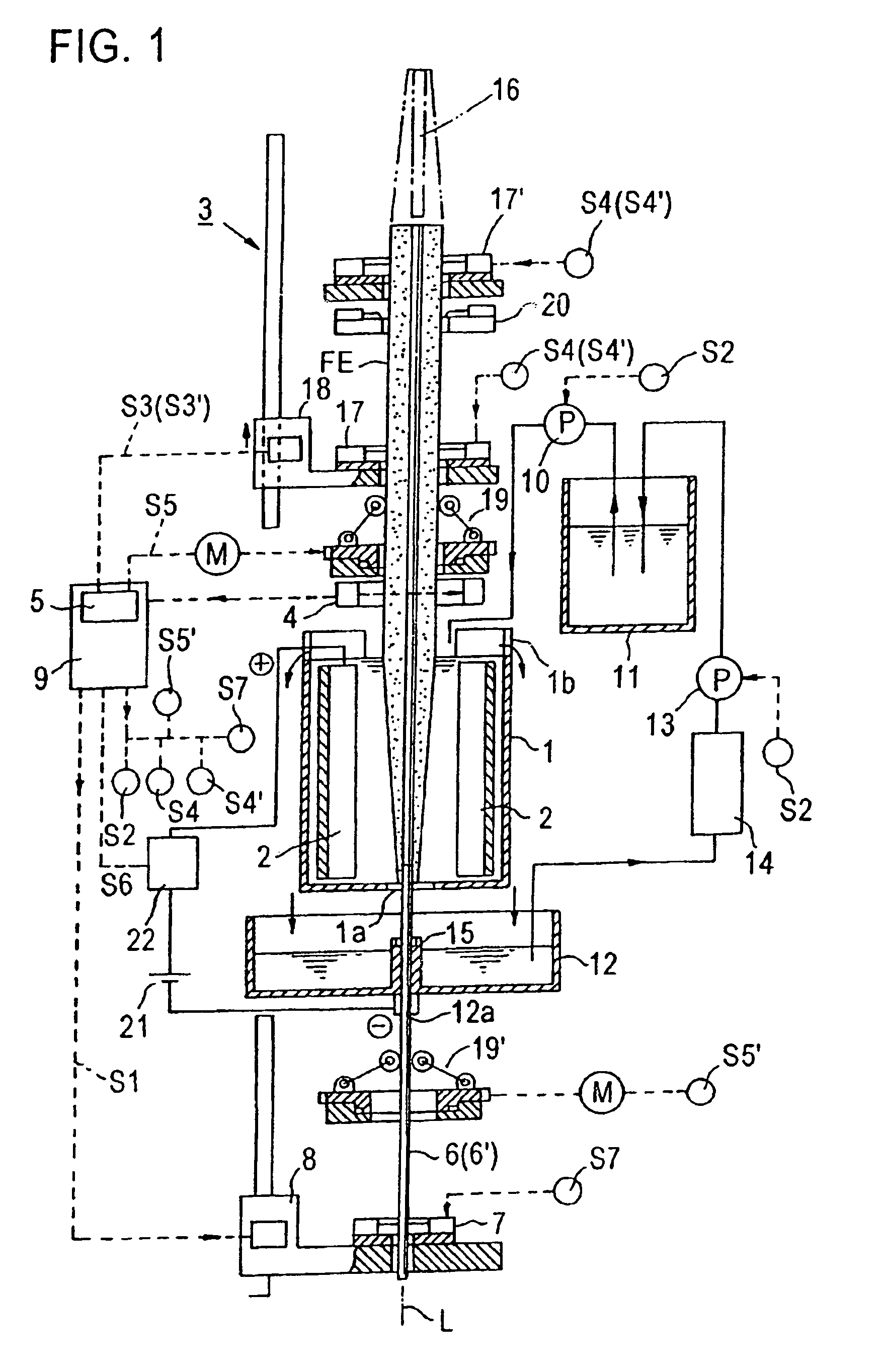
[0051]The first embodiment of the present invention is described as follows, with reference to the aforementioned figures. As shown by FIGS. 1 to 4, the present invention's device for manufacturing metal ferrules used for optical fibers grows, in the electroforming cistern 1, a tube-shaped electroformed layer (ferrule material) FE that has an internal hole whose diameter is the same as the internal diameter of the cylindrical metal ferrule (it is a connector element) to be manufactured on the cathode side of the electroforming cistern 1, with said cathode side being opposite the anode 2 (which is desirably composed of an insoluble material such as platinum, gold, or titanium). Said manufacturing device is furnished, in particular, with:[0052](1) a lifter 3 for lifting a tube-shaped electroformed layer FE that is grown in the electroforming cistern 1,[0053](2) a measurer 4 for measuring the external diameter of the electroformed layer FE outside the electroforming...
second embodiment
The Second Embodiment
[0082]The second embodiment of the present invention is described as follows. Herein, the cathode core member 16 (dummy) shown in the first embodiment is not used. As a cathode opposed to the anode furnished in the electroforming cistern 1, the internal-diameter-formation member 6, whose external diameter is the same as the internal diameter of the cylindrical metal ferrule to be manufactured, is supplied upwardly through the bottom portion of the aforementioned electroforming cistern to be directly supported at its upper end by the support 17. In the electroforming liquid, around said internal-diameter-formation member 6, a tube-shaped electroformed layer FE having a cylindrical internal hole is grown on the cathode side of the electroforming cistern 1 (see FIG. 6). Also, the support 7 and the elevator 8 are not used. Further, the other constituents and controls are the same as in the first embodiment and are not described herein.
[0083]In this case, for the cut...
third embodiment
The Third Embodiment
[0084]The third embodiment of the present invention is described as follows. Herein, instead of the internal-diameter-formation member 6 in the second embodiment, a cylindrical member 6′ whose internal diameter is the same as the internal diameter of the necessary metal ferrule (ferrule) is used (see FIG. 8). Also, the material thereof is desirably the same as the metal accumulated around the member 6′ by the electroforming (for example, when a nickel alloy is accumulated, the member 6′ is of the same material). In this case, the cutting edge 20, which is used in the first embodiment (see FIG. 4), cuts the member 6′ together with the electroformed layer in the surroundings thereof. Herein, the member 6′, as a part of the ferrule, is left in the electroformed layer. Further, the other constituents and controls are the same as in the first embodiment and are not described herein.
PUM
 Abstract
Description
Claims
Application Information
 - R&D
- Intellectual Property
- Life Sciences
- Materials
- Tech Scout
- Unparalleled Data Quality
- Higher Quality Content
- 60% Fewer Hallucinations
Browse by: Latest US Patents, China's latest patents, Technical Efficacy Thesaurus, Application Domain, Technology Topic, Popular Technical Reports.
© 2025 PatSnap. All rights reserved.Legal|Privacy policy|Modern Slavery Act Transparency Statement|Sitemap|About US| Contact US: help@patsnap.com


