
Isothermal Reactor

a technology of isothermal reactor and heat exchanger, which is applied in the direction of indirect heat exchanger, physical/chemical process catalyst, lighting and heating apparatus, etc., can solve the problems of complex radial configuration of heat exchanger in terms of construction and assembly, non-homogenous catalytic area between heat exchangers, and inability to achieve optimal temperature distribution, simple and effective isothermal reactor

Active Publication Date: 2010-06-03
CASALE SA
View PDF6 Cites 4 Cited by
  • Summary
  • Abstract
  • Description
  • Claims
  • Application Information

AI Technical Summary

Benefits of technology

[0020]Thanks to the present invention, it is advantageously possible to simply and effectively make an isothermal reactor with a high heat exchange coefficient, to the great advantage of the conversion yield and energy consumption.
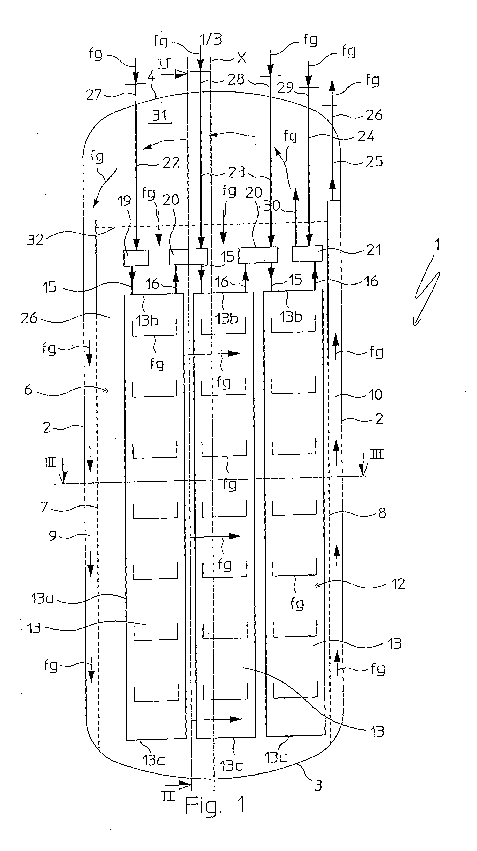
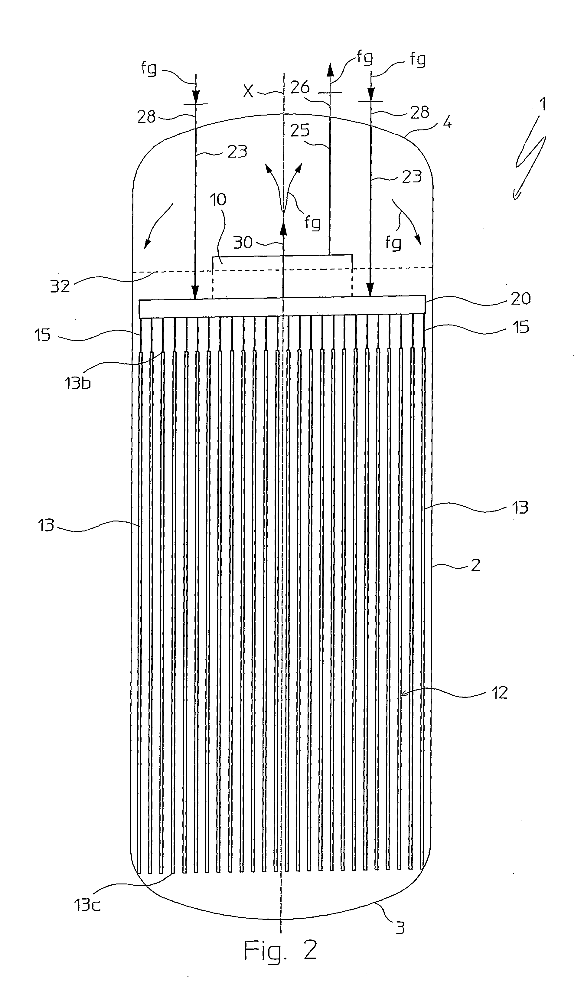
[0021]Indeed, unlike the radial configuration of isothermal reactors of the prior art, in the present invention the heat exchangers are arranged substantially parallel to each other and this means that it is possible to obtain homogeneous catalytic areas (i.e. substantially constant sections) between adjacent exchangers to be crossed by the gaseous flow comprising reactants and reaction products in a direction perpendicular to the axis of the shell and in portions substantially parallel to each other.
[0022]This involves that each portion of gaseous flow comprising reactants and reaction products is able to exchange heat efficiently with the relevant heat exchangers along the entire respective catalytic section for crossing of the catalytic bed, thus obtaining an optimal temperature distribution inside the catalytic bed even for highly exothermal or endothermal reactions, to the great advantage of the conversion yield inside it and the relative energy consumption.
[0023]It should be observed that the parallel instead of radial arrangement of the heat exchangers advantageously allows the portions of the aforementioned gaseous flow to cross the catalytic bed with a practically uniform speed.
[0024]Moreover, the sections for the crossing of the catalytic bed by said gaseous flow comprising reactants and reaction products can be made smaller than those of an analogous radial configuration. As a result, therefore, said gaseous flow crosses the catalytic bed at a greater speed and there is less load loss, which allows the number and / or size of the catalytic beds to be reduced, to the great advantage of the greater simplicity of construction and assembly of the isothermal reactors of the invention compared to known radial isothermal reactors as well as lower maintenance costs.
[0025]Thus, for example, to produce ammonia, it is possible, thanks to the present invention, to use just one catalytic bed without having problems of the reactant gases crossing the catalytic bed at a too low speed, whereas, in known isothermal reactors with radial configuration it is necessary to have many overlapped catalytic beds to avoid the reactant gas g the catalytic beds at too low speed with a consequent low heat exchange coefficient between the reactant gases and the heat exchangers. Therefore, an isothermal reactor for producing ammonia according to the invention has a substantial simplification of its structure with respect to an analogous isothermal reactor of the prior art since it is possible to considerably reduce the number of connections (for example collector ducts, distributor ducts, etc.) necessary to place the various catalytic beds in communication as well as to distribute the heat exchange fluid in the various heat exchangers immersed in said catalytic beds.

Problems solved by technology

Although advantageous from some points of view, the aforementioned isothermal reactors with radial configuration have a series of drawbacks including that they have a non-homogeneous catalytic area between the heat exchangers due to their radial arrangement.
As a result, the heat exchange is not always optimal between the gaseous flow that crosses the catalytic bed and the heat exchange fluid in the heat exchangers, in particular in the area of the catalytic bed in which the distance between adjacent exchangers is greater, as well as a non-uniform crossing speed of the catalytic bed by said gaseous flow, since the latter is subjected to variations in speed according to the lesser or respectively greater section for crossing the catalytic bed.
Moreover, in known isothermal reactors, the radial configuration of the heat exchangers is complicated in terms of construction and assembly.

Method used


Image

  • Isothermal Reactor
  • Isothermal Reactor
  • Isothermal Reactor

Examples


Embodiment Construction

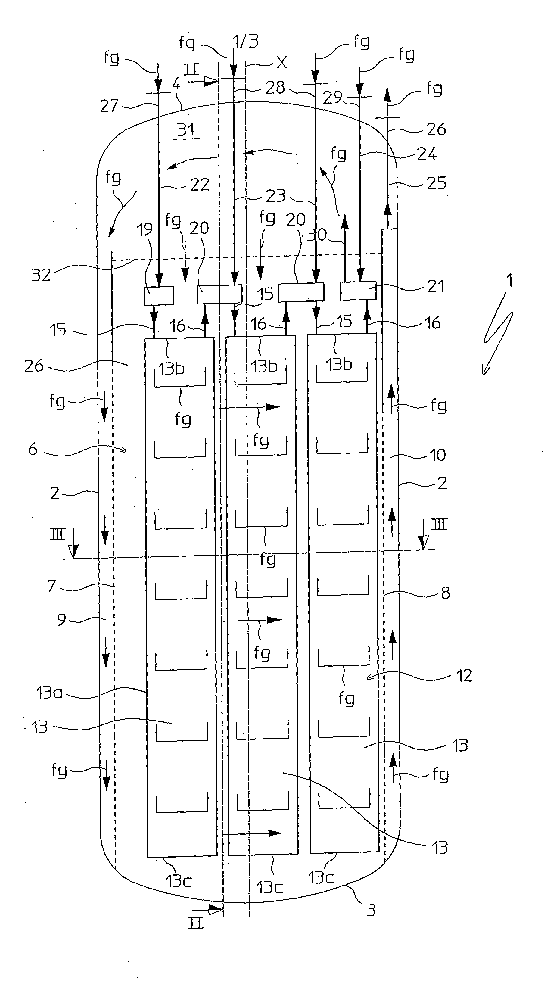
[0031]With reference to the aforementioned figures, reference numeral 1 globally indicates a pseudo-isothermal chemical reactor according to the present invention for the synthesis of chemical substances, in particular ammonia.

[0032]Said reactor 1 comprises a cylindrical shell 2, with longitudinal axis X, defined at the opposite ends by lower and upper bottoms 3, 4. In the example of the figures, the longitudinal axis X is vertical.

[0033]Inside the cylindrical shell 2 a catalytic bed, generically indicated with 6, is housed and supported in a per se conventional way, the catalytic bed 6 being delimited laterally by opposite perforated side walls 7 and 8 for the inlet of a gaseous flow of reactants and for the outlet of a gaseous flow comprising reactants and reaction products. The catalytic bed 6 is also open on top, i.e. equipped with grids for containing the catalyst that are permeable to gas, not represented as they are conventional. The filling level of the catalytic bed 6 by th...


PUM

PropertyMeasurementUnit
temperatureaaaaaaaaaa
heat exchange efficiencyaaaaaaaaaa
areaaaaaaaaaaa

Abstract

The present invention concerns an isothermal reactor (1) for carrying out exothermal or endothermal heterogeneous reactions comprising: —a substantially cylindrical outer shell (2) with longitudinal axis (X), —at least one catalytic bed (6) extending in the shell (2) and comprising opposite perforated side walls (7, 8) respectively for the inlet of a gaseous flow of reactants and for the outlet of a gaseous flow comprising reaction products, and —a heat exchange unit (12) immersed in said at least one catalytic bed (6) and crossed by a heat exchange fluid, characterised in that said heat exchange unit (12) comprises at least one succession of heat exchangers (13) arranged substantially parallel to each other and substantially parallel to the direction in which said at least one catalytic bed (6) is crossed by said gaseous flow of reactants.

Description

FIELD OF APPLICATION[0001]In its most general aspect, the present invention concerns an isothermal reactor for carrying out exothermal or endothermal heterogeneous reactions, comprising:[0002]a substantially cylindrical outer shell with longitudinal axis,[0003]at least one catalytic bed extending in the shell and comprising opposite perforated side walls respectively for the inlet of a gaseous flow of reactants and for the outlet of a gaseous flow comprising reaction products[0004]a heat exchange unit immersed in said catalytic bed and crossed by a heat exchange fluid.[0005]Such a reactor is particularly useful for carrying out exothermal or endothermal reactions performed in substantially isothermal conditions, in other words conditions in which the reaction temperature is controlled in a narrow range of values around a predetermined value.[0006]In the remainder of the description and in the subsequent claims, a reactor of the aforementioned type is identified with the terms: pseud...

Claims


Application Information

Patent Timeline
Patent Type & Authority Applications(United States)
IPC IPC(8): B01J8/02F28D7/00
CPCB01J8/0221F28D9/00B01J8/0496B01J19/249B01J2208/00115B01J2208/00123B01J2208/00132B01J2208/0015B01J2208/022B01J2219/2453B01J2219/2458B01J2219/2462B01J2219/247B01J2219/2481B01J2219/2485F28D7/0058B01J8/0285
Inventor FILIPPI, ERMANNORIZZI, ENRICOTAROZZO, MIRCO
Owner CASALE SA
Learn More