
Circular saw blade with thermal barrier coating

a technology of thermal barrier coating and circular saw blade, which is applied in the direction of band saws, saw chains, manufacturing tools, etc., can solve the problems of cutting edge deviating laterally, exacerbated blade deviation, and increased sawdust spillag

Inactive Publication Date: 2010-05-20
SIMONDS INT L L C
View PDF32 Cites 25 Cited by
  • Summary
  • Abstract
  • Description
  • Claims
  • Application Information

AI Technical Summary

Benefits of technology

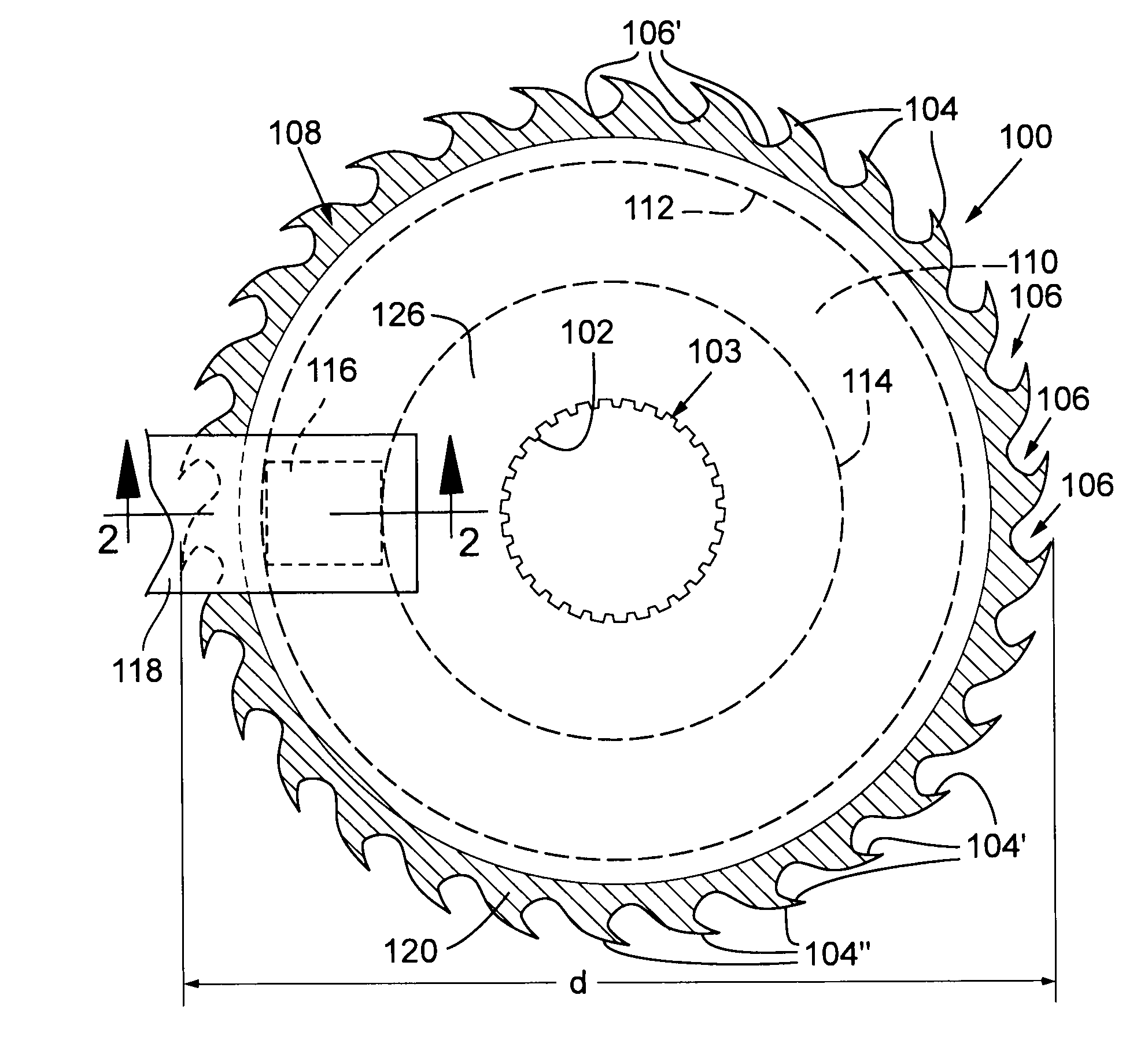
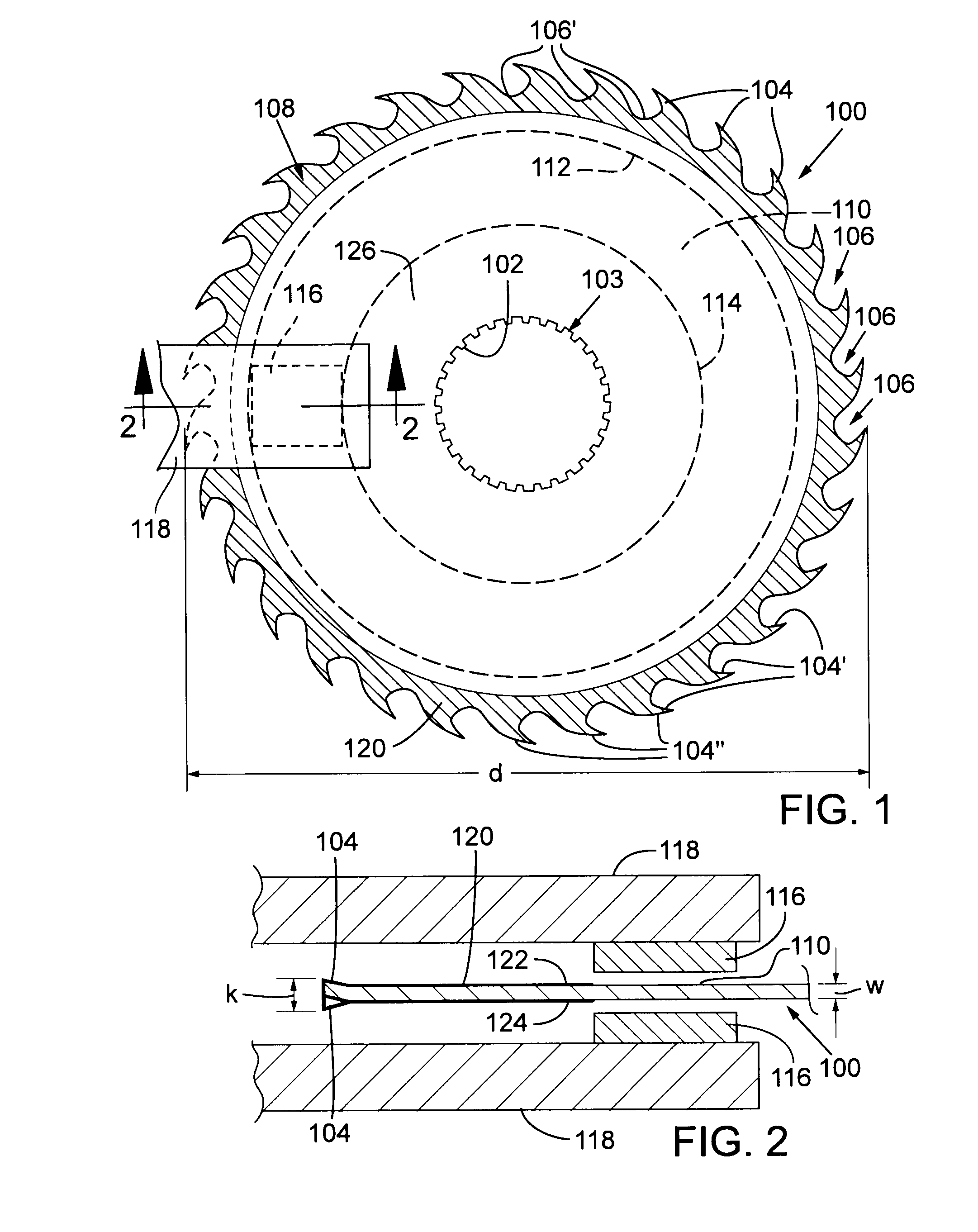
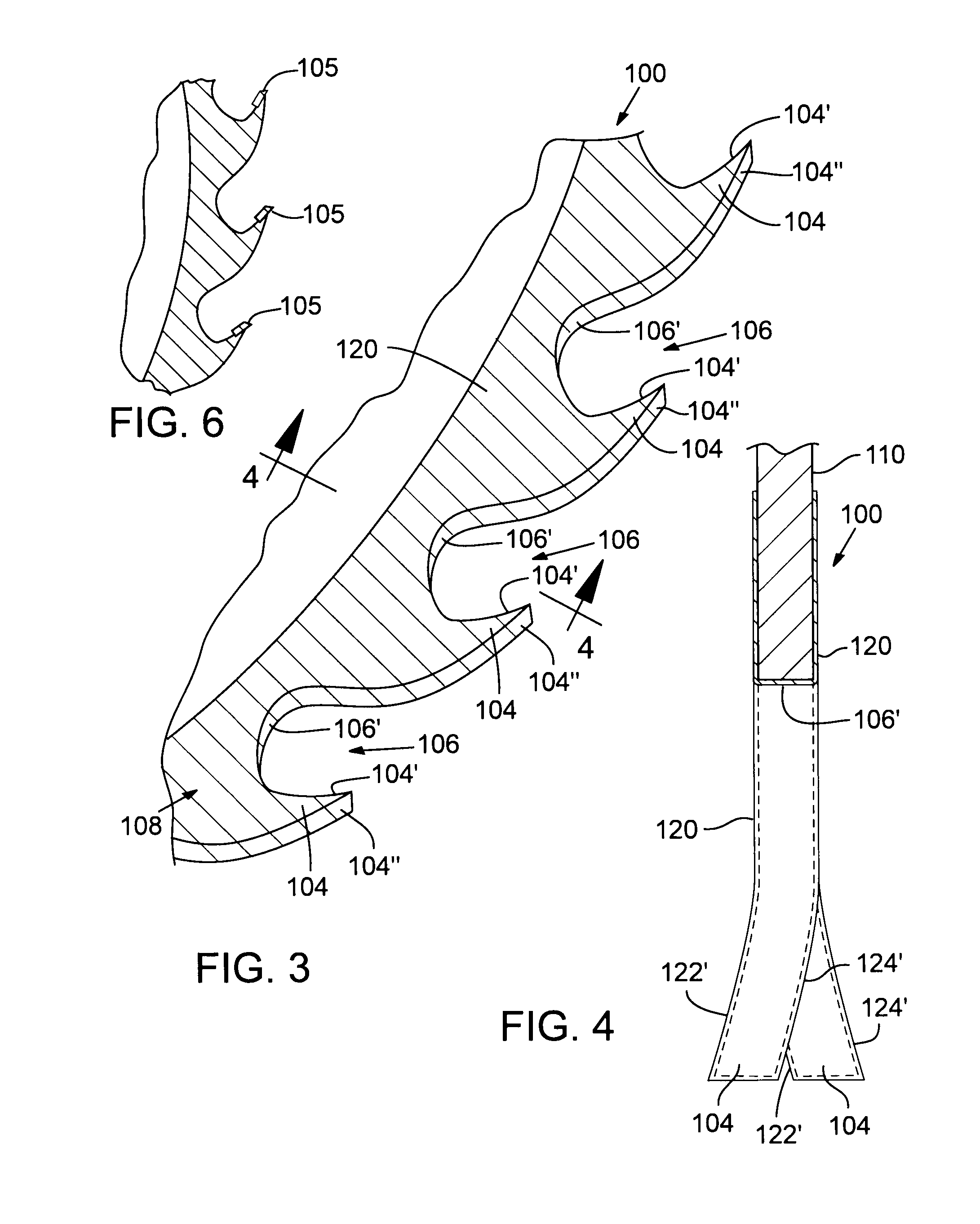
[0004]According to one embodiment, a thermal barrier coating is applied to an outer margin of a circular saw blade to inhibit abrupt increases in temperature of the outer margin during cutting operation. The thermal barrier coating may be applied on opposing major surfaces of the circular saw blade in the outer margin. For example, the thermal barrier coating may cover opposing major surfaces of the cutting teeth. The thermal barrier coating may also cover the cutting edges of the cutting teeth and the blade tooth gullets that separate the cutting teeth. The thermal barrier coating may include a carbide and / or an oxide, and may be applied by using a plasma spray process or another coating process.

Problems solved by technology

In conventional circular saw systems, sawdust spillage along the sides of the saw blade causes friction that tends to increase the temperature of its outer margin, which increases internal stresses that may cause the cutting edge to deviate laterally.
Moreover, the gullets between the cutting teeth tend to wear over time, which increases sawdust spillage and exacerbates blade deviation.
In some circumstances, an unacceptable amount of lateral deviation of the cutting edge occurs after only a few hours of operation.

Method used


Image

  • Circular saw blade with thermal barrier coating
  • Circular saw blade with thermal barrier coating
  • Circular saw blade with thermal barrier coating

Examples


Embodiment Construction

[0012]With reference to the above-listed drawings, this section describes particular embodiments and their detailed construction and operation. The embodiments described herein are set forth by way of illustration only and not limitation. Those skilled in the art will recognize in light of the teachings herein that there is a range of equivalents to the example embodiments described herein. Most notably, other embodiments are possible, variations can be made to the embodiments described herein, and there may be equivalents to the components, parts, or steps that make up the described embodiments.

[0013]For the sake of clarity and conciseness, certain aspects of components or steps of certain embodiments are presented without undue detail where such detail would be apparent to those skilled in the art in light of the teachings herein and / or where such detail would obfuscate an understanding of more pertinent aspects of the embodiments.

[0014]According to one embodiment, a thermal barri...


PUM

PropertyMeasurementUnit
Thicknessaaaaaaaaaa
Thicknessaaaaaaaaaa
Lengthaaaaaaaaaa

Abstract

A circular saw blade includes a ceramic coating applied to opposing major surfaces in an outer margin of the circular saw blade where cutting teeth of the saw blade are arranged in spaced-apart relation and separated by blade tooth gullets. The ceramic coating inhibits abrupt increases in temperature of the outer margin during cutting operation to thereby inhibit the cutting teeth from deviating laterally. Methods of making saw blades include applying a ceramic coating to the outer margin using a plasma spray process or another coating process.

Description

RELATED APPLICATION[0001]This application claims the benefit under 35 U.S.C. §119(e) of U.S. Provisional Application No. 61 / 115,885, filed Nov. 18, 2008, which is incorporated herein by reference.TECHNICAL FIELD[0002]The present disclosure relates generally to cutting systems and more particularly to circular saw blades such as circular saw blades for lumber mills and methods of making circular saw blades.BACKGROUND INFORMATION[0003]Circular saw systems for lumber mills are described in U.S. Pat. Nos. 3,285,302 and 3,623,520, incorporated herein by reference for background only. These patents describe gang saws having guide arms with wear pads formed of babbitt metal. The guide arms and wear pads improve the accuracy of the cut and reduce the size of the kerf by preventing the saw blade cutting edge from wandering laterally. The wear pads abut opposing sides of the blade radially inward from the outer margin of the blade where the cutting teeth are distributed. In conventional circu...

Claims


Application Information

Patent Timeline
IPC IPC(8): B27B33/08B23D61/02B05D5/00B05D1/08
CPCB23D61/026C23C4/10B23D61/028Y10T83/9319
Inventor RUTHVEN, JAMES P.MACEY, DAVID S.
Owner SIMONDS INT L L C
Learn More