Dental abutment including fillet

a technology of dental abutments and fillets, applied in the field of dental abutments, can solve the problems of difficult design of small shapes that resist breakage, high stress on the creation of dental abutments made of ceramics, and high brittleness of ceramics, so as to reduce stress

Active Publication Date: 2010-05-13
ASTRA TECH SE
View PDF10 Cites 20 Cited by
  • Summary
  • Abstract
  • Description
  • Claims
  • Application Information

AI Technical Summary

Benefits of technology

[0008]Another aspect of the invention is directed to a dental abutment comprising a head portion located at an upper end of the abutment and constructed to support a prosthetic tooth replacement and soft tissue adjacent the head portion, an anti-rotation feature located at a lower end of the abutment and constructed to mate with a dental implant, and a fillet located at an interface between the head portion and the anti-rotation feature (e.g., to reduce stress at the interface). The fillet may have a closed perimeter and may form a concavity at least partly in one of the anti-rotation feature and the head portion. A radial dimension of the fillet along a vertical cross-section of the fillet may be at least 0.1 mm.

Problems solved by technology

However, metal abutments have certain aesthetic drawbacks.
Ceramics, however, are much more brittle than titanium, such that it is challenging to design small shapes that resist breakage.
Creation of a structurally sound ceramic dental abutment therefore presents many challenges.

Method used


Image

  • Dental abutment including fillet
  • Dental abutment including fillet
  • Dental abutment including fillet

Examples


Embodiment Construction

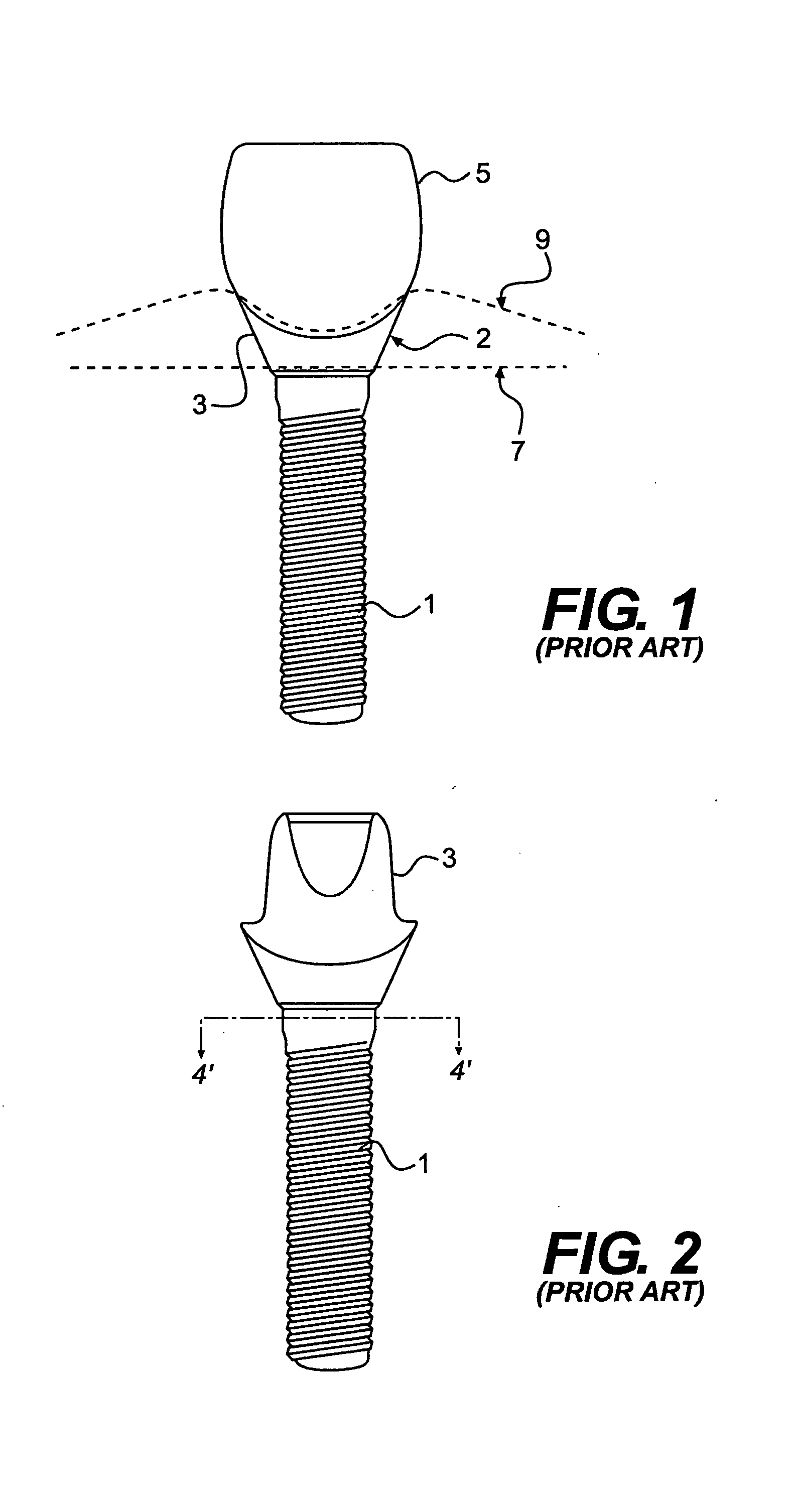
[0035]FIGS. 1 and 2 illustrate a conventional artificial tooth replacement comprising a dental implant 1, an abutment 3, and a crown 5. In use, the implant 1 is anchored within a jawbone, the profile of which is shown by line 7. The abutment 3 is fixedly attached to the top of the implant 1, as shown in FIG. 2, and serves as an interface between the implant 1 and the crown 5. The crown 5 is positioned over the abutment 3 and is fixedly attached thereto. A tapered portion 2 of the abutment 3 may be positioned below the gum line 9 (as shown in FIG. 1) or at least only partially above the gum line 9. Thus, if the abutment 3 is formed of titanium, the grayish color of the abutment 3 may be visible above the gum line 9 or through the thin soft tissue of the gum just below the gum line 9. The titanium of the abutment therefore may give the artificial tooth replacement an unnatural and generally undesirable appearance.

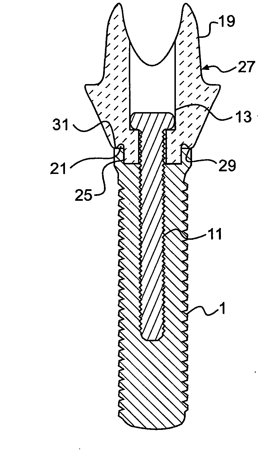
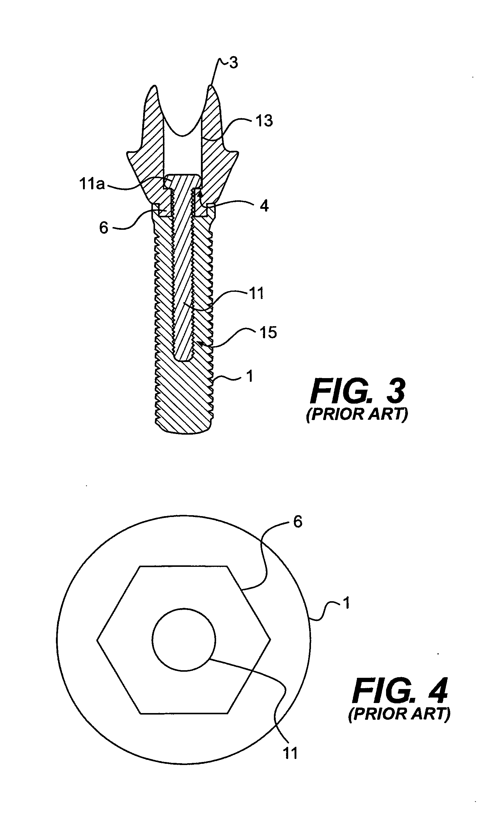
[0036]FIG. 3 illustrates a vertical cross-sectional view of a typical pr...


PUM


Abstract

Exemplary embodiments relate to a dental abutment and methods of forming the same. The abutment (19) may include a head portion (27) located at an upper end of the abutment and constructed to support a prosthetic tooth replacement and soft tissue adjacent the head portion, an anti-rotation feature (25) located at a lower end of the abutment and constructed to mate with a dental implant, and a fillet (21) located at an interface between the head portion and the anti-rotation feature. The fillet may reduce a risk of fracture at the interface between the head portion and the anti-rotation feature. In some examples, the abutment may be formed at least partially of a ceramic material.

Description

FIELD OF THE INVENTION[0001]This invention is directed to the field of dental abutments.BACKGROUND OF THE INVENTION[0002]Artificial tooth replacements are used in prosthetic dentistry to improve the appearance and / or functionality of a patient's teeth. A common artificial tooth replacement comprises a dental implant that is anchored within the bone, an abutment fastened to the implant with a screw, and a functional and aesthetic tooth replacement (a crown) positioned on the abutment. The abutment serves as the interface between the implant and the crown.[0003]Traditionally, both the implant and the abutment are formed of metal (e.g., titanium or gold alloys), and the crown is often made entirely of ceramic.[0004]However, metal abutments have certain aesthetic drawbacks. First, where a patient's soft tissue (or gum tissue) are thinner, for example in the anterior, or front, region of the mouth, the gray color of the metal abutment can be seen through the soft tissue. In patients wher...

Claims


Application Information

Patent Timeline
Patent Type & Authority Applications(United States)
IPC IPC(8): A61C8/00G05B19/4097
CPCA61C8/005A61C8/0066A61C8/006A61C8/0059A61C8/00
Inventor GRANT, BETHANY F.HANNOOSH, JAMES G.
Owner ASTRA TECH SE
Why Eureka
Try Eureka