
System method and apparatus for dry-in, dry-out, low defect laser dicing using proximity technology

a laser dicing and proximity technology, applied in the direction of manufacturing tools, cleaning using liquids, welding/soldering/cutting articles, etc., can solve the problems of limiting or at least reducing the adhesion of particles to the surrounding surface, process problems can occur, and die damag

Inactive Publication Date: 2010-05-06
LAM RES CORP
View PDF3 Cites 5 Cited by
  • Summary
  • Abstract
  • Description
  • Claims
  • Application Information

AI Technical Summary

Problems solved by technology

Further, the water from the water jet tends to spread out over the surrounding surface of the substrate and thereby somewhat limit or at least reduce the adhesion of the particles to the surrounding surface of the substrate.
Unfortunately, the water-jet-guided laser is a wet process and the resulting dies must then be thoroughly cleaned of any particle contamination.
During this additional processing and handling the dies can be damaged and / or process problems can occur.

Method used


Image

  • System method and apparatus for dry-in, dry-out, low defect laser dicing using proximity technology
  • System method and apparatus for dry-in, dry-out, low defect laser dicing using proximity technology
  • System method and apparatus for dry-in, dry-out, low defect laser dicing using proximity technology

Examples


Embodiment Construction

[0043]Several exemplary embodiments for a system and method for dicing substrates without the need of a subsequent cleaning and drying process will now be described. It will be apparent to those skilled in the art that the present invention may be practiced without some or all of the specific details set forth herein.

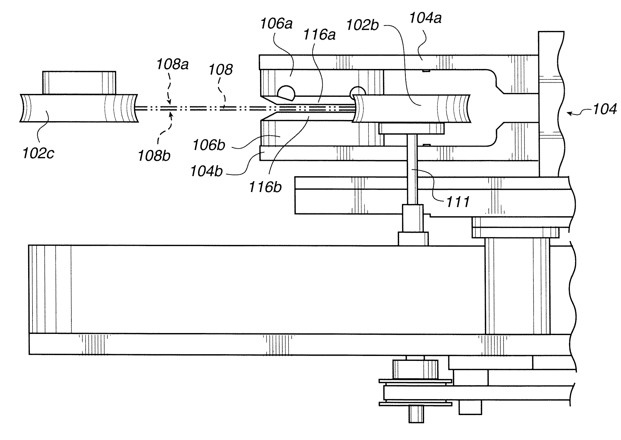
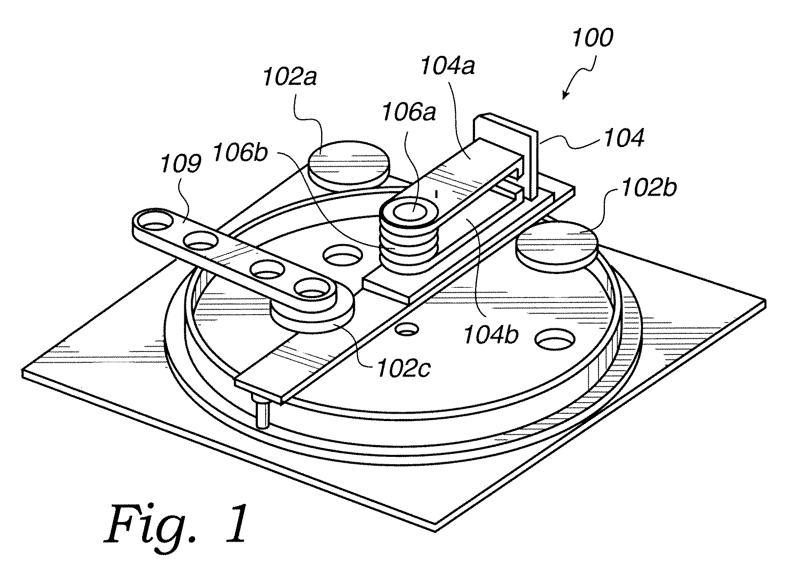
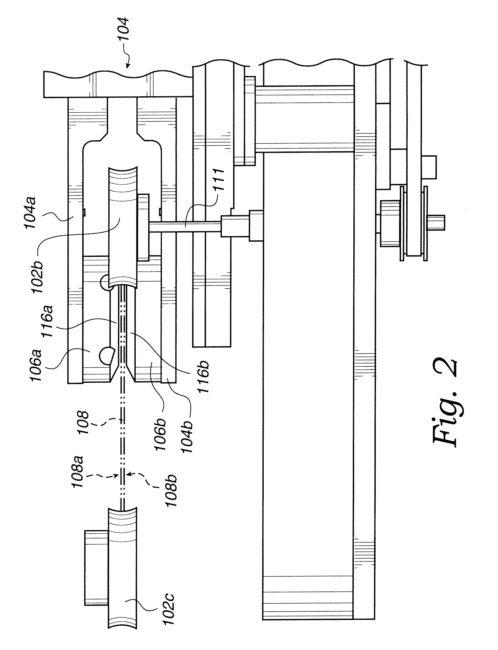
[0044]The present invention provides a system that combines a proximity head supporting a dynamic liquid meniscus with a dicing laser. In this system substantially all of the particles generated by the laser are immediately removed from the surface of the substrate by the dynamic flow of the fluid in the meniscus. Further, the dynamic liquid meniscus performs a cleaning and / or rinsing process and a drying process simultaneously with the laser dicing process thereby providing a dry-in dry-out substrate dicing process. Further still, the fluid (i.e., DIW) used to form the dynamic liquid meniscus can be recaptured, filtered to remove particles or other contaminants and reu...


PUM


Abstract

A substrate processing system includes a first, movable surface tension gradient device, a dicing device and a system controller. The first, movable surface tension gradient device is capable of supporting a first process within a first meniscus. The first meniscus being supported between the first surface tension gradient device and a first surface of the substrate. The first movable surface tension gradient device capable of being moved relative to the first surface of the substrate. The dicing device is oriented to a desired dicing location. The desired dicing location being encompassed by the meniscus. The system controller is coupled to the dicing device and the surface tension gradient device. The system controller includes a process recipe. A method for dicing a substrate is also described. The method of dicing a substrate including placing a substrate in a substrate dicing system, forming a meniscus between a proximity head and a first surface of the substrate, dicing the substrate at a desired dicing location and simultaneously capturing any particles and contaminants generated by dicing the substrate within the meniscus, the meniscus including the desired dicing location and moving the meniscus in a desired dicing direction.

Description

CROSS REFERENCE TO RELATED APPLICATIONS[0001]This application is a divisional of and claims priority from U.S. patent application Ser. No. 11 / 016,381 filed on Dec. 16, 2004 and entitled “System, Method and Apparatus for Dry-In, Dry-Out, Low Defect Laser Dicing Using Proximity Technology,” by Boyd et al., which is incorporated herein by reference in its entirety for all purposes. The present application and U.S. patent application Ser. No. 11 / 016,381 are continuation-in-part of and claim priority from U.S. patent application Ser. No. 10 / 606,022 filed on Jun. 24, 2003 and entitled “System and Method for Integrating In-Situ Metrology Within a Wafer Process,” by Boyd et al., which is incorporated herein by reference in its entirety for all purposes.BACKGROUND OF THE INVENTION[0002]1. Field of the Invention[0003]The present invention relates generally to dicing substrates, and more particularly, to methods and systems for simultaneously cleaning and dicing substrates.[0004]2. Description...

Claims


Application Information

Patent Timeline
Patent Type & Authority Applications(United States)
IPC IPC(8): B23K26/00G03F7/20H01L21/00
CPCB08B3/04H01L21/02052H01L21/02057H01L21/3065H01L21/67028H01L21/67034B23K26/1224H01L21/67092H01L21/78B23K2103/50B23K26/146B23K26/40H01L21/67051
Inventor BOYD, JOHN M.REDEKER, FRED C.
Owner LAM RES CORP
Learn More