
Apparatus and method for Rapid Biodiesel Fuel Production

a biodiesel fuel and apparatus technology, applied in biofuels, chemical/physical/physicochemical processes, fuels, etc., can solve the problems of cavitation and high shear, and achieve high instantaneous temperatures and high shear

Inactive Publication Date: 2010-05-06
TALWAR MAHESH +2
View PDF5 Cites 28 Cited by
  • Summary
  • Abstract
  • Description
  • Claims
  • Application Information

AI Technical Summary

Benefits of technology

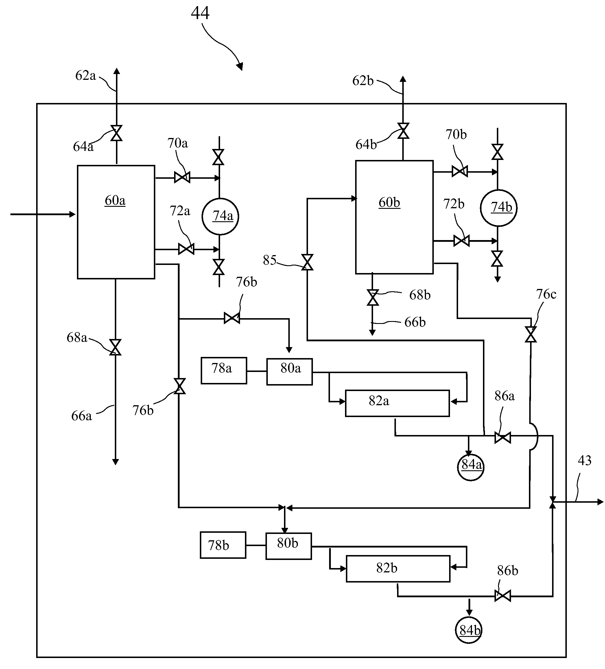
[0008]The present invention addresses the above and other needs by providing a biodiesel fuel production system including a packed bed column followed by a high pressure kinetic reactor to achieve nearly complete production of biodiesel fuel while minimizing undesired by products. High surface area made available through packed bed columns provide 40 to 70 percent reaction completion in a first phase. The remaining reaction is completed in the high pressure kinetic reactor which is preferably a high pressure cavitation chamber. The present invention allows reactions to proceed at 40 degrees centigrade as opposed to 80 to 100 degrees centigrade required by known fast reactors, thus saving energy costs. Near stoichiometric quantities of methanol are sufficient for reaction completion in the present invention compared to 50 to 100 percent excess methanol required in known systems. The present invention allows all of the chemicals to be added ahead of the packed bed column as opposed to spilt chemicals being added in a conventional reactor system into first stage and then second stage. Known systems require a limit of Free Fatty Acid (FFA) content in the incoming feed oil to less than 2.5 percent, and required refined, bleached, degummed oil for feed. The present invention processes degummed crude palm oil with five to eight percent FFA with minimal soaps formation as well as tallow with 2.8% FFA with complete success. In known processes, FFA will react into soaps. The present invention does not produce such soaps.
[0009]In accordance with one aspect of the invention, there is provided a continuous flow through system for rapid production of biodiesel fuel. The continuous flow system includes flow meters and / or pumps, a venturi static mixer, packed bed columns for a first phase, and a high pressure kinetic reactor for completing the rapid production of the biodiesel fuel. Following metering, the ingredients are introduced into the venturi static mixer which allows thorough mixing of the ingredients into one homogeneous stream. The homogeneous stream then enters the packed bed column which is designed for three minutes residence time. The partially reacted ingredients then enter the high pressure kinetic reactor. Fluids exiting the high pressure kinetic reactor are completely reacted into biodiesel fuel and byproduct glycerine.
[0011]In accordance with yet another aspect of the invention, there is provided a kinetic reactor comprising a high pressure cavitation reactor based on principles of hydro cavitation and high shear whereby the cavitation forces break fluid molecules into nano molecules with very high instantaneous temperatures and availability of large surface areas which allow complete reaction without external heat. The high pressure kinetic reactor is operated at 700-1000 psi pressure and is composed of an adjustable need valve design in which fluid entering the kinetic reactor is forced through opposing orifices at opposite ends of the kinetic reactor creating impinging streams. The resulting collision of the streams causes high shear and cavitation to complete the reaction producing the biodiesel fuel. The opposing orifices are adjustable through the internal needle valve to provide the desired effect.

Problems solved by technology

The resulting collision of the streams causes high shear and cavitation to complete the reaction producing the biodiesel fuel.

Method used


Image

  • Apparatus and method for Rapid Biodiesel Fuel Production
  • Apparatus and method for Rapid Biodiesel Fuel Production
  • Apparatus and method for Rapid Biodiesel Fuel Production

Examples


Embodiment Construction

[0027]The following description is of the best mode presently contemplated for carrying out the invention. This description is not to be taken in a limiting sense, but is made merely for the purpose of describing one or more preferred embodiments of the invention. The scope of the invention should be determined with reference to the claims.

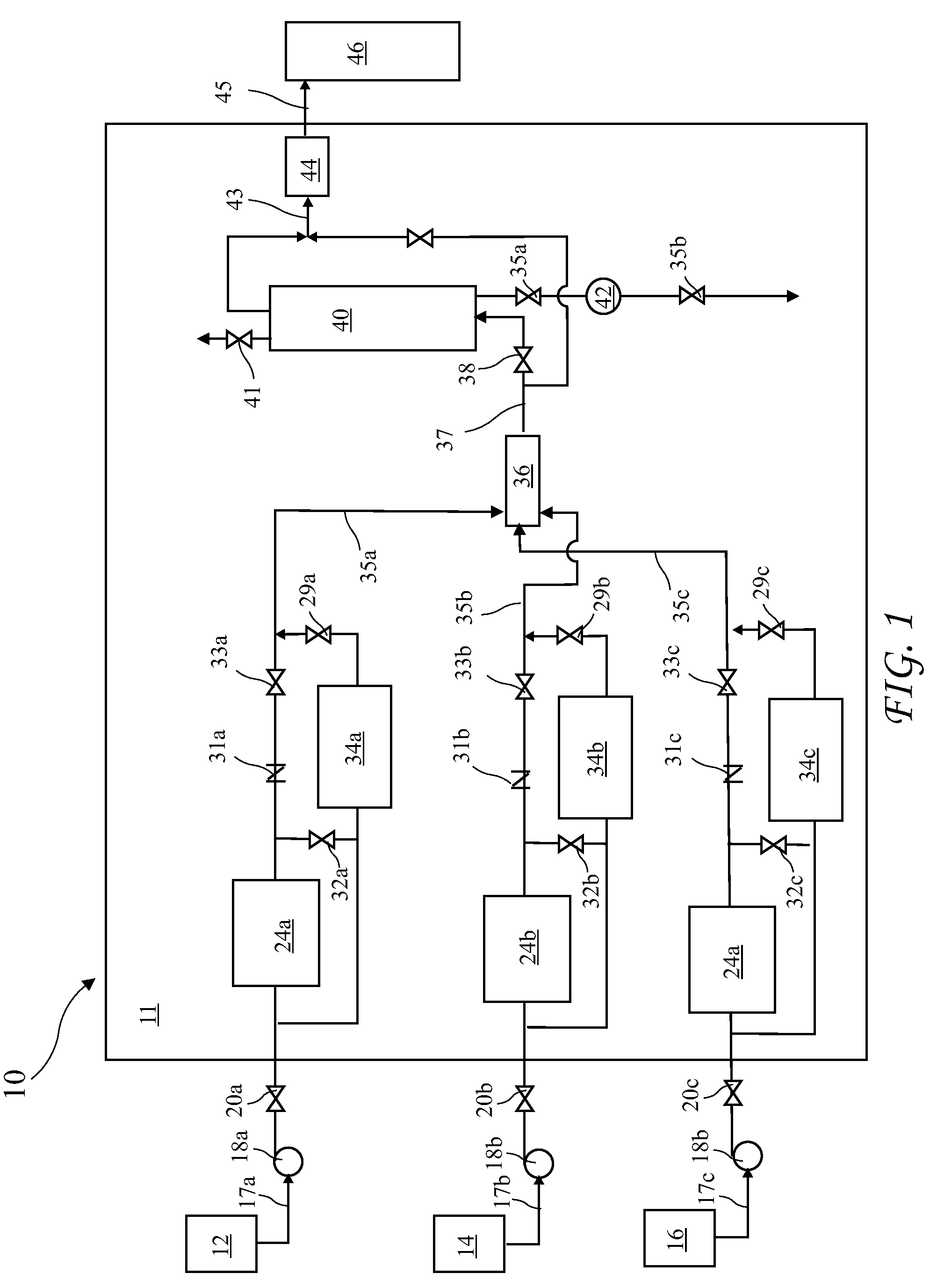
[0028]A high level diagram of a biodiesel fuel processing system 10 according to the present invention is shown in FIG. 1. The biodiesel fuel processing system 10 may be pre-assembled on a skid 11 for delivery to a biodiesel fuel production facility. The biodiesel fuel processing system 10 includes two sequential phases for biodiesel fuel production. The first phase is performed in a packed column 40 and the second phase is performed in a high pressure kinetic reactor assembly 44. Feed oil, alcohol, and a catalyst are combined and reacted to produce the biodiesel fuel. The biodiesel fuel production facility includes a catalyst tank 12, an alcohol ...


PUM

PropertyMeasurementUnit
diameteraaaaaaaaaa
diameteraaaaaaaaaa
pressureaaaaaaaaaa

Abstract

Apparatus and method for rapid production of biodiesel fuel. The apparatus includes a packed column followed by a high pressure kinetic reactor. A homogeneous stream of feed oil (vegetable oil or animal fat), methanol, and a catalyst is metered, mixed, fed into a packed column, and finally into the high pressure kinetic reactor where the conversion into biodiesel fuel is completed. The packed column is packed with rings (either Raschig rings or pall rings or equivalent). The homogeneous stream enters from the bottom with rings kept in a fluidized bed state to allow greatest surface area for reaction to take place. Approximately 40 to 70 percent reaction is typically achieved in the packed column. The high pressure kinetic reactor receives the partially reacted homogeneous stream and breaks fluid molecules into nano molecules with very high instantaneous temperatures and availability of large surface areas which allow complete reaction without external heat.

Description

BACKGROUND OF THE INVENTION[0001]The present invention relates to the production of biodiesel fuel and in particular to rapid production of biodiesel fuel.[0002]Recent increases in the cost of petroleum have raised both economic and national security concerns. Petroleum costs translate directly into gasoline and diesel fuel costs which impact both personal and commercial expenses. Various alternatives for powering vehicles have been proposed and in various stages of maturity. These alternatives including: natural gas; electricity; hydrogen; and biodiesel. Biodiesel is an alternative fuel for conventional diesel engines and offers advantages including less pollution, but presently is not available in large quantities.[0003]Biodiesel is produced from ingredients comprising feed oils (vegetable oils or animal fats), a small percentage of alcohol, and a catalyst. The process for producing biodiesel fuel, commonly called transesterification, generally includes a tradeoff between reaction...

Claims


Application Information

Patent Timeline
Patent Type & Authority Applications(United States)
IPC IPC(8): C10L1/18B01J19/00
CPCB01J8/20B01J19/008B01J19/26B01J2219/00006B01J2219/0004B01J2219/00164B01J2219/30215C10G2300/1011C10L1/026Y02E50/13Y02P30/20Y02E50/10
Inventor TALWAR, MAHESHGILL, JAGROOP S.PIRO, JR., ANGELO C.
Owner TALWAR MAHESH
Learn More