
Biomass conversion process

a biomass and conversion process technology, applied in biofuels, waste based fuels, organic chemistry, etc., can solve the problems of increasing capital and operating costs, raising financial and ethical issues, and low conversion efficiency, so as to improve the conversion of biomass into fuels, reduce costs, and reduce equipment costs.

Inactive Publication Date: 2010-04-29
MARD INC
View PDF8 Cites 77 Cited by
  • Summary
  • Abstract
  • Description
  • Claims
  • Application Information

AI Technical Summary

Benefits of technology

[0007]In various embodiments the invention includes methods, apparatuses, kits, and compositions for converting cellulosic (e.g., including ligno- and hemi-cellulosic) material in biomass (e.g., including edible and inedible portions) into fuels and / or specialty chemicals under conditions that can mitigate equipment cost, energy cost, and / or degradation or undesirable reaction of conversion product. Examples of fuels include light gases (ethane, propane, butane), naphtha, and distillates (jet fuel, diesel, heating oil). Examples of chemicals include light olefins (ethylene, propylene, butylenes), acids (like formic and acetic), aldehydes, alcohols (ethanol, propanol, butanol, phenols), ketones, furans, and the like. For example, the technology includes preparing solid biomass particles for catalytic conversion, which can improve conversion of the biomass into fuels and / or specialty chemicals in conventional petroleum refining processes (e.g., known petrochemical refining units). The technology also includes adapting existing refinery processes for processing biomass (e.g., change operating parameters, catalyst, and feedstock), retrofitting existing refinery process units for processing biomass (e.g., adding an extra riser for biomass catalytic cracking or adding a solid biomass feeder system to introduce biomass), and constructing new, purpose-built biomass reactors (e.g., employ commercially available conventional reactor components). Thus, the methods, apparatuses, kits, and compositions can reduce the cost and increase the availability of fuel and / or specialty chemicals derived from biomass. Preparation can have a synergistic effect, reducing the temperature necessary for catalytic or pyrolytic conversion of the biomass and / or increasing the conversion efficiency of the biomass, as well as facilitating processing in conventional refining units.

Problems solved by technology

However, using refined biomass feedstock for fuels and specialty chemicals can divert food sources from animal and human consumption, raising financial and ethical issues.
Producing fuels and specialty chemicals from biomass can require specialized conversion processes and / or refineries, which are distinct from and incompatible with conventional petroleum-based conversion processes and refineries.
Thus, the wide-spread use and implementation of biomass to produce fuels and specialty faces many challenges, because large-scale production facilities are not widely available and are expensive to build.
Furthermore existing processes can require extreme conditions (e.g., high temperature and / or pressure, which increases capital and operating costs), require expensive catalysts, suffer low conversion efficiency (e.g., incomplete conversion or inability to converts ligno- and hemi-cellulosic material), and / or suffer poor product selectivity.
Another challenge to the use of biomass feedstock to produce fuel or specialty chemical products is high acidity (i.e., low pH) in bio-oil intermediates produced from pyrolyzing the biomass feedstock.
High acidity can cause problems such as corrosion in conventional fluid catalytic cracking (FCC) equipment and thus can require costly upgrades to conventional FCC units to resist corrosion (e.g., upgrades with exotic, corrosion-resistant alloys such as a HASTELLOY® alloy available from Haynes International, Inc.).

Method used


Image

  • Biomass conversion process
  • Biomass conversion process
  • Biomass conversion process

Examples


examples

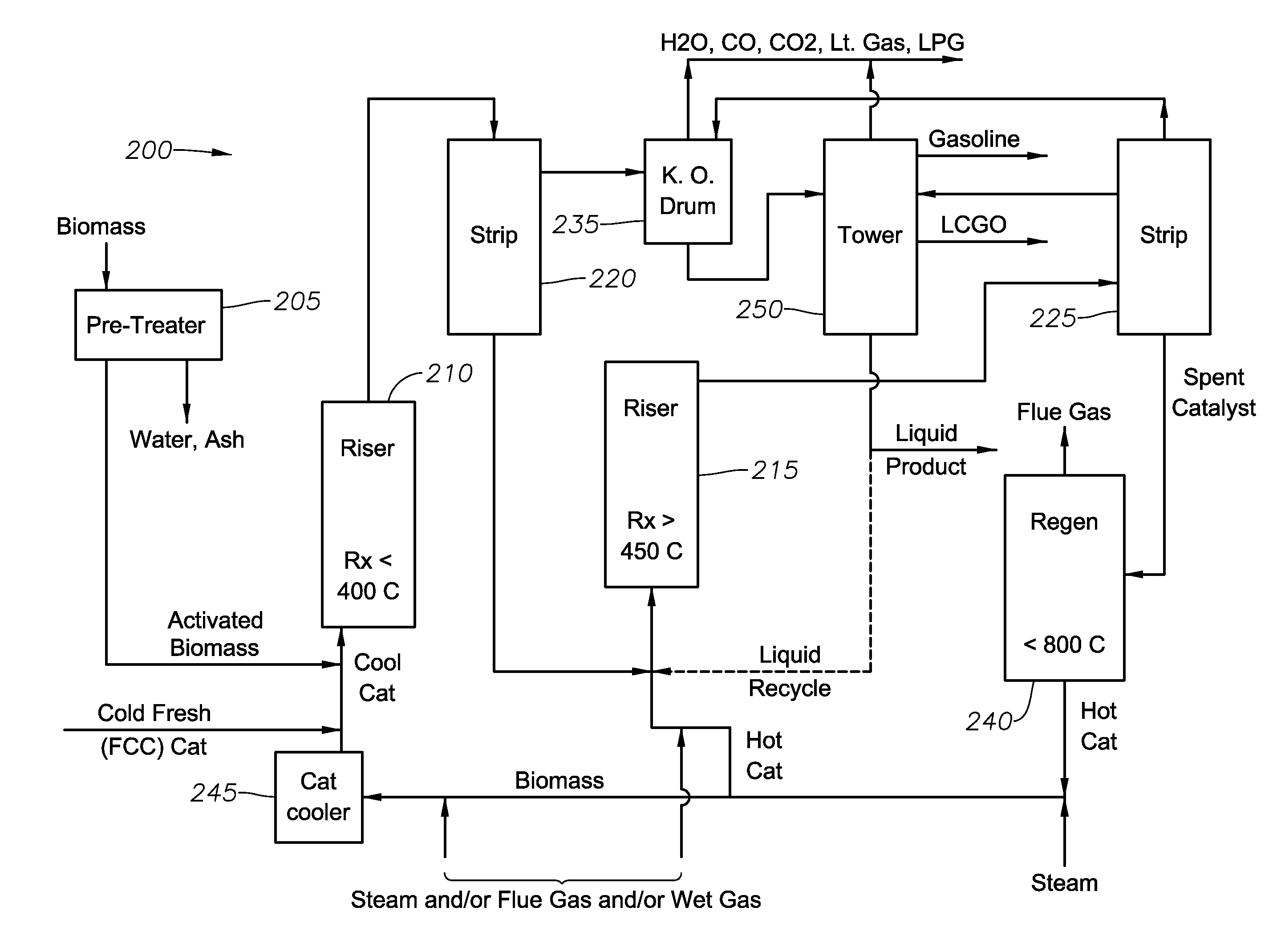
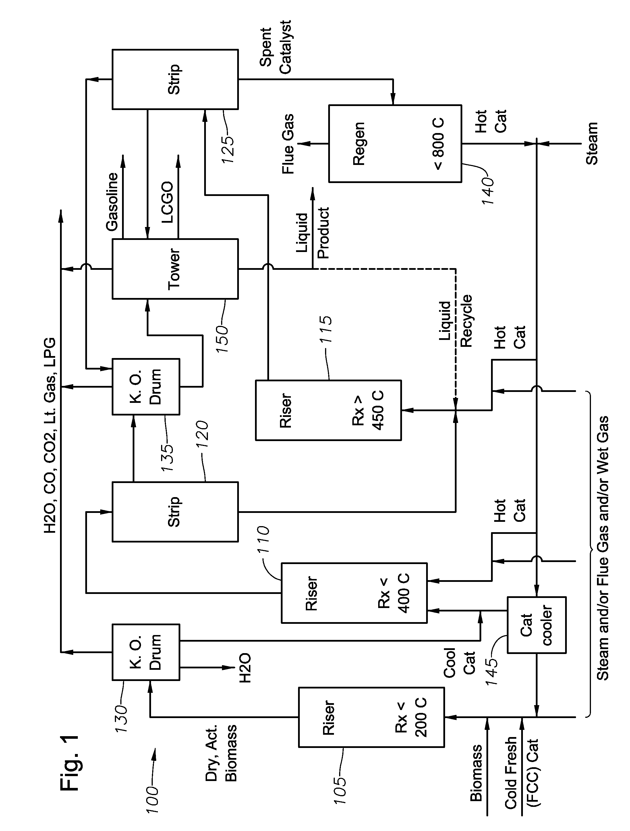
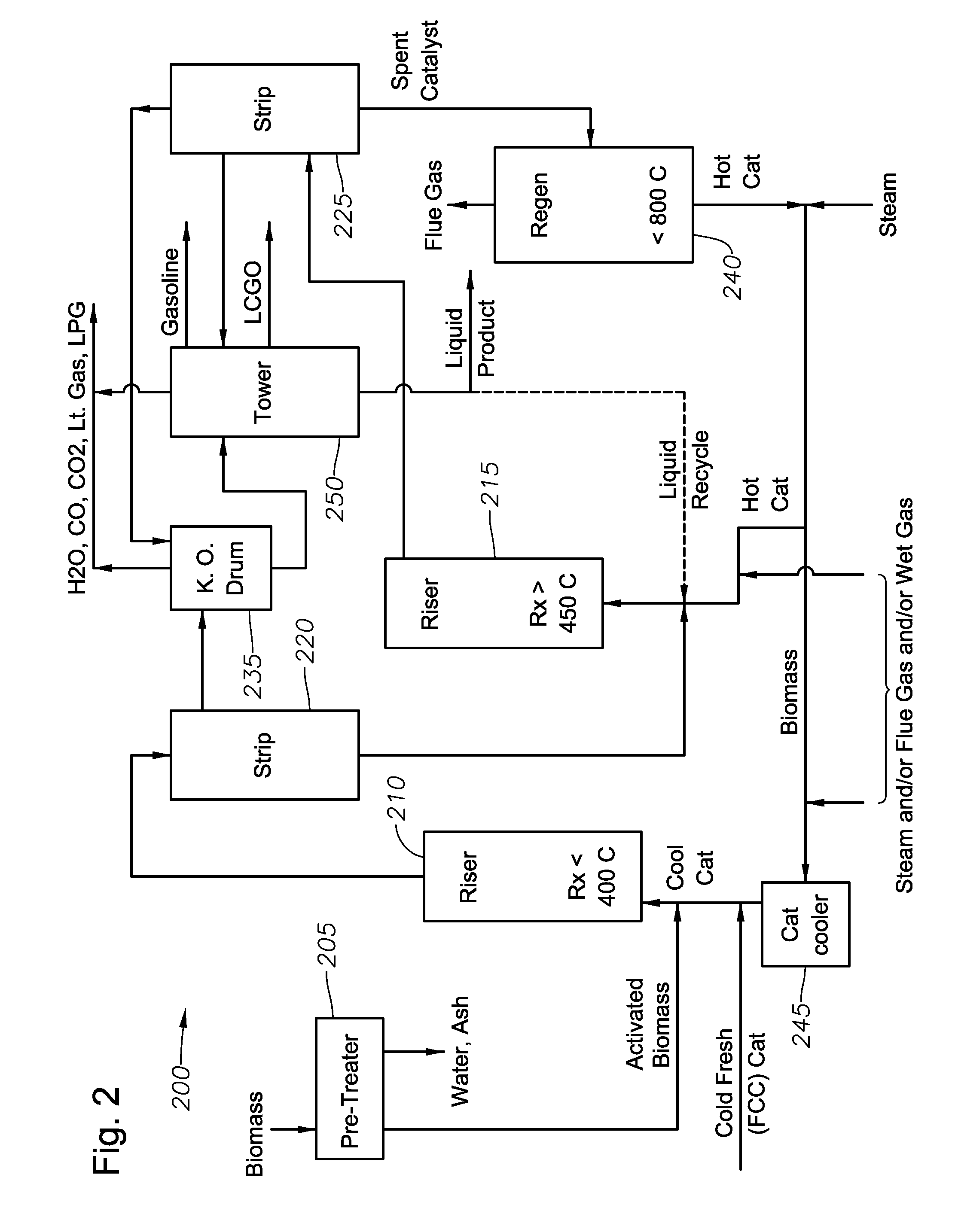
[0068]FIGS. 1 and 2 show exemplary systems for preparing and processing biomass with catalyst. The technology also includes methods corresponding to the operation of the systems (i.e., apparatuses) corresponding to FIGS. 1 and 2. The technology also includes kits for setting up the apparatuses and carrying out the methods corresponding to FIGS. 1 and 2. The technology also includes products and intermediates, and fractions thereof, corresponding to FIGS. 1 and 2. It should be understood that one skilled in the art could modify or adapt the exemplary systems, or any other system described herein, to convert biomass into fuels or specialty chemicals. For example, catalyst, reaction vessel(s), pretreatment, and reaction conditions can be selected based upon the type of biomass and the desired product. In some embodiments, the processing can occur in a single vessel. In other embodiments, two or more vessels can be used.

[0069]In various embodiments, the intermediates include hydrocarbon...


PUM

PropertyMeasurementUnit
temperatureaaaaaaaaaa

Abstract

A method for converting solid biomass into hydrocarbons includes contacting the solid biomass with a catalyst in a first riser operated at a temperature in the range of from about 50° C. to about 200° C. to thereby produce a first biomass-catalyst mixture and a first product comprising hydrocarbons; a) separating the first product from the first biomass-catalyst mixture; c) charging the first biomass-catalyst mixture to a second riser operated at a temperature in the range of from about 200° C. to about 400° C. to thereby produce a second biomass-catalyst mixture and a second product comprising hydrocarbons; d) separating the second product from the second biomass-catalyst mixture; e) charging the second biomass-catalyst mixture to a third riser operated at a temperature greater than about 450° C. to thereby produce a spent catalyst and a third product comprising hydrocarbons; and f) separating the third effluent from the spent catalyst.

Description

CROSS REFERENCE TO RELATED APPLICATIONS[0001]Related Application No. 61 / 076,962, entitled “Co-Processing Solid Biomass in a Conventional Petroleum Refining Process Unit” and filed on Jun. 30, 2008 by Yanik et al., is incorporated by reference herein in its entirety.FIELD OF THE INVENTION[0002]The invention relates to producing a fuel or specialty chemical product from biomass through a chemical process. The invention relates more particularly to preparing solid biomass for catalytic conversion and to deoxygenating, catalytically cracking, and converting the biomass into a fuel or specialty chemical product.BACKGROUND OF THE INVENTION[0003]Biomass, in particular biomass of plant origin, is recognized as an abundant potential source of fuels and specialty chemicals. See, for example, “Energy production from biomass,” by P. McKendry—Bioresource Technology 83 (2002) P 37-46 and “Coordinated development of leading biomass pretreatment technologies” by Wyman et al., Bioresource Technology...

Claims


Application Information

Patent Timeline
Patent Type & Authority Applications(United States)
IPC IPC(8): C07C1/00
CPCC10G1/08C10G1/006C10B49/22C10B53/02C10B57/02C10G3/42C10G3/57Y02P20/145Y02P30/20Y02E50/30Y02E50/10
Inventor YANIK, STEVEBARTEK, ROBERTO'CONNOR, PAULSTAMIRES, DENNISBRADY, MICHAEL
Owner MARD INC
Learn More