Eureka AIR delivers breakthrough ideas for toughest innovation challenges, trusted by R&D personnel around the world.

Battery pack, battery-mounted device and connection structure for battery pack

a battery pack and battery-mounted technology, applied in the field of batteries, can solve the problems of increased damage, abnormality in the battery, and blown high-temperature and pressure gas,

Active Publication Date: 2010-04-29
PANASONIC CORP
View PDF2 Cites 26 Cited by
  • Summary
  • Abstract
  • Description
  • Claims
  • Application Information

AI Technical Summary

Benefits of technology

[0008]The present invention was developed for the purpose of solving the above shortcomings and an object thereof is to provide a battery pack capable of securing safety by preventing the battery pack from entering a burning state even if a battery contained in the battery pack releases high-temperature gas in an abnormal state.
[0010]Since the temperature of the gas is reduced to such a temperature as not to lead to a burning state before the gas is exhausted to the outside in the present invention, the burning of the gas exhausted to the outside can be suppressed.

Problems solved by technology

However, even if the conventional protection means is provided, abnormality may occur in the battery and high-temperature and pressure gas may be blown from the inside of the battery.
In such a case, it is thought that a casing of a pack containing the battery is broken, melted or burnt, whereby the high-temperature and pressure gas leaks to the outside of the battery pack or is burnt and spreads burning inside and outside the battery pack to increase damage.
However, since the gas released from the batteries has high temperature, high pressure and high inflammability, it may ignite upon being brought into contact with or mixed with oxygen in the air in some cases.
Therefore, even other batteries start a runaway effect and the entire battery pack is broken, thereby increasing damage.

Method used


Image

  • Battery pack, battery-mounted device and connection structure for battery pack
  • Battery pack, battery-mounted device and connection structure for battery pack
  • Battery pack, battery-mounted device and connection structure for battery pack

Examples


example 1a

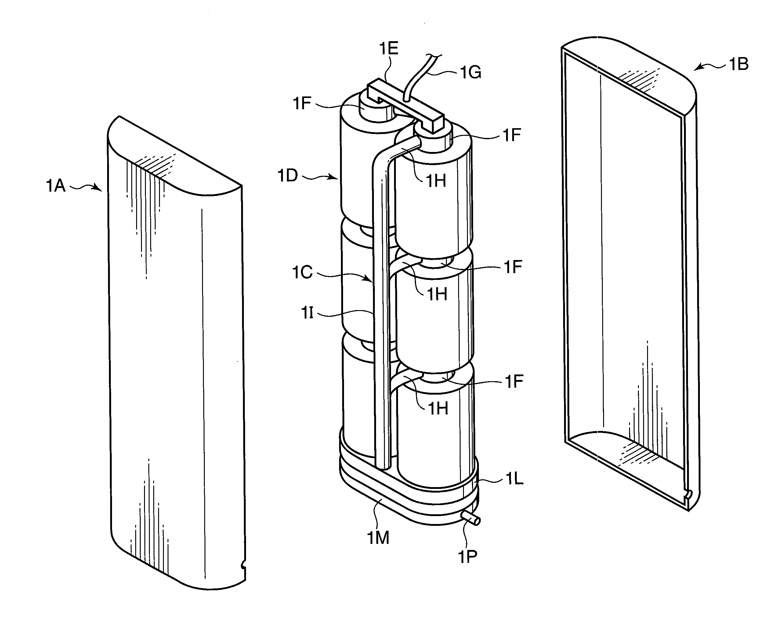
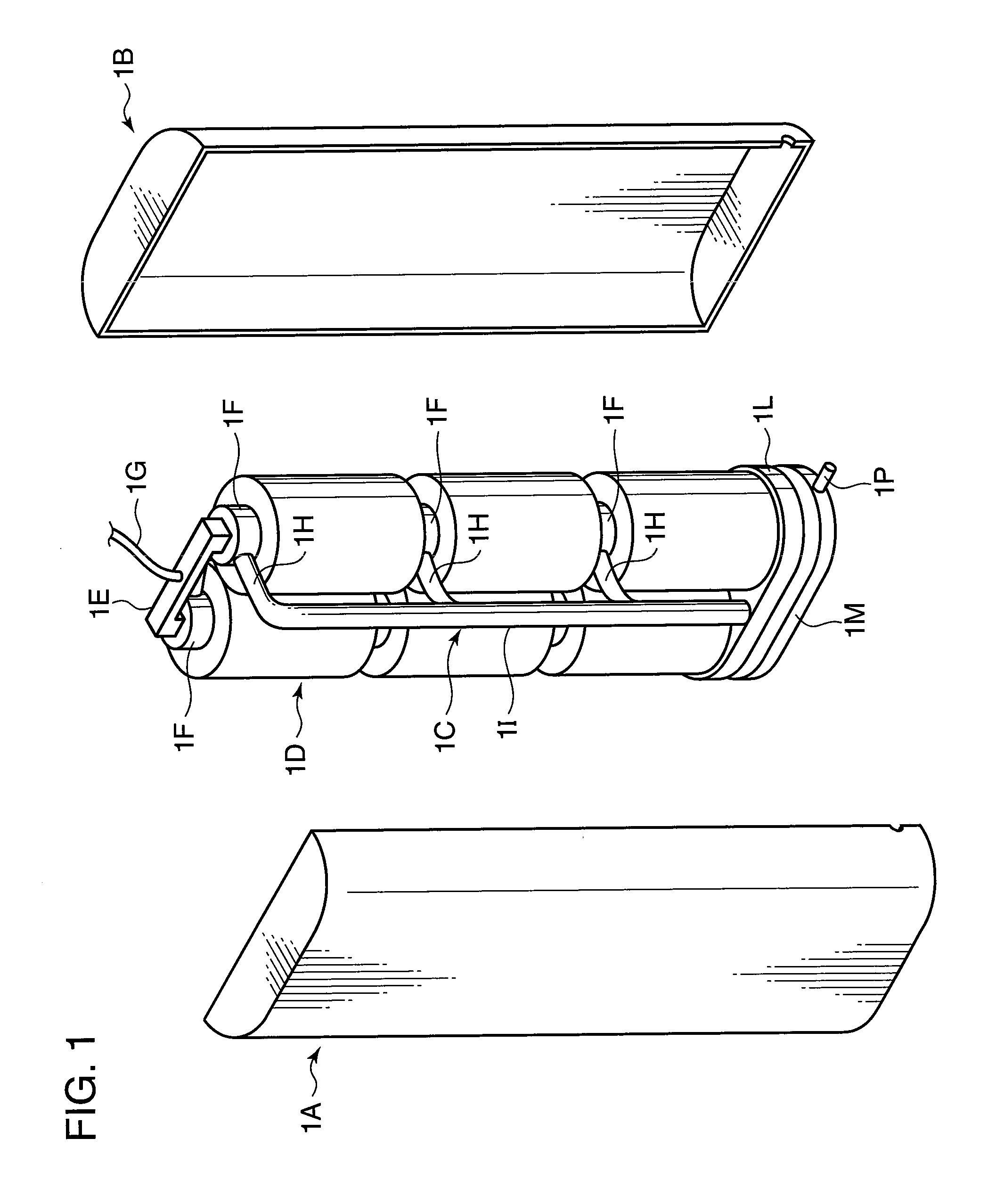
[0077]The assembled batteries 1D and the exhaust duct 1C shown in FIG. 1 were contained in the battery pack 1A, 1B and the outer peripheries of the battery pack 1A, 1B were welded. At this time, the completed battery pack was charged with constant current, constant voltage up to 13.5 V by bypassing an overcharge protection circuit and a current interrupt device (CID) of the cells of the pack normally charged up to 12.6 V with a maximum current at the time of charging set to 3 A and a current at the end of charging set to 0.1 A, whereby a battery pack of Example 1 was obtained.

example 1b

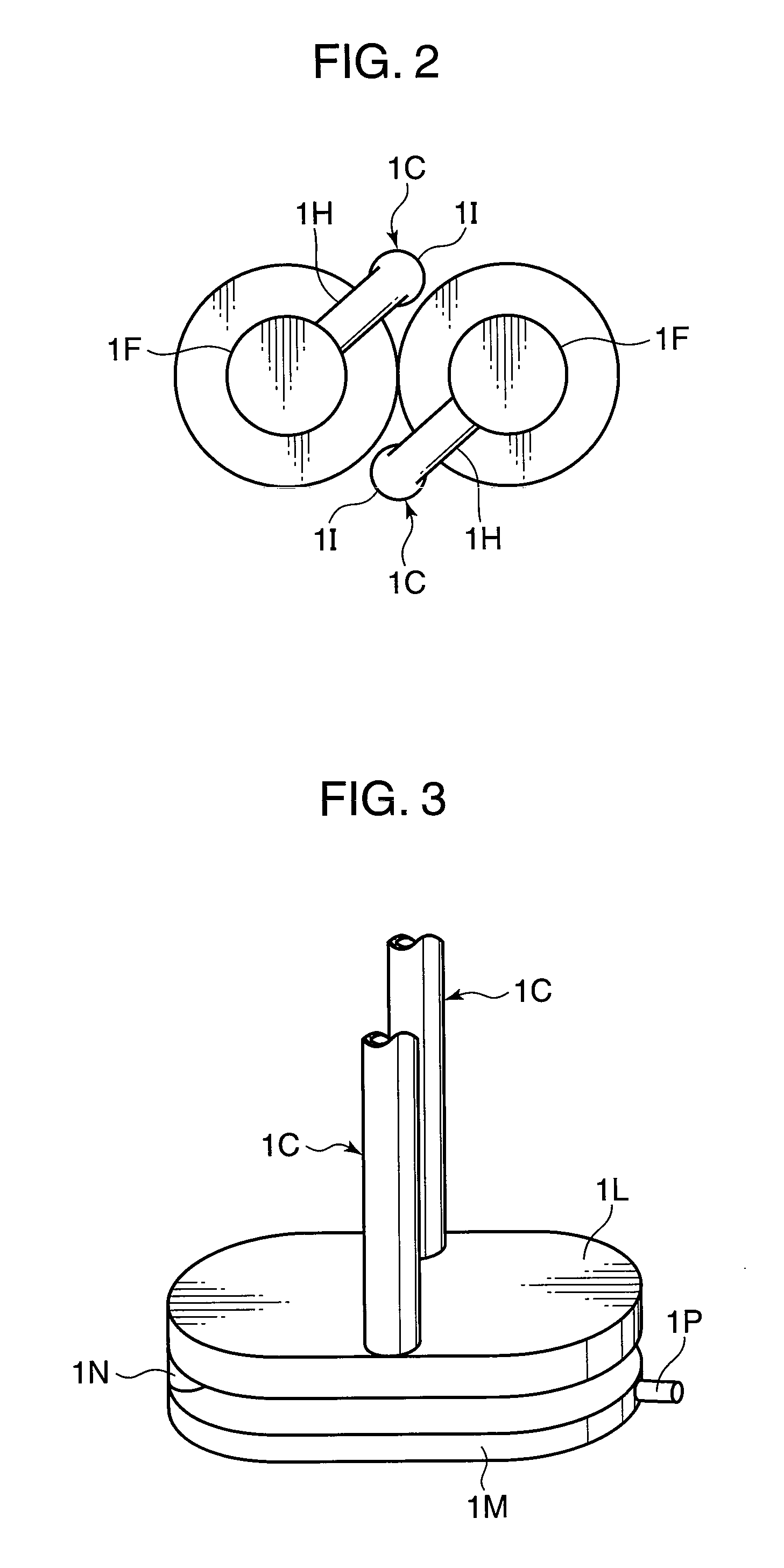
[0078]A porous ceramic plate (industrial ceramic honeycomb: manufactured by NGK Insulators, Ltd.) having a thickness of 1 mm was bonded to the inner part of the spark trapping portion 1M. An arrangement position of this porous ceramic plate was on a wail facing a wall portion connected with the communication pipe 1N. A battery pack was manufactured similar to Example 1A except for the above to obtain a battery pack of Example 1B.

example 1c

[0079]A gel plate (manufactured by Sekisui Plastics Co., Ltd.) having a thickness of 1 mm was bonded to the inner part of the spark trapping portion 1M. An arrangement position of this gel plate was on the wall facing the wall portion connected with the communication pipe 1N. A battery pack was manufactured similar to Example 1A except for the above to obtain battery pack of Example 1C.


PUM

PropertyMeasurementUnit
thicknessaaaaaaaaaa
heightaaaaaaaaaa
heightaaaaaaaaaa

Abstract

It is aimed to provide a battery pack capable of securing safety by preventing A battery contained in the battery pack from entering a burning state even if the battery releases high-temperature gas in an abnormal state. An exhaust duct 1C for permitting the flow of gas released from the battery is provided and the gas is exhausted to the outside after reducing the temperature thereof in the exhaust duct 1C. A flow passage area of the exhaust duct 1C is in the range of not less than 0.5 mm2 and not more than 15 mm2 per 1 Ah of the battery capacity. The exhaust duct 1C is provided with a gas cooling portion 1L and a spark trapping portion 1M.

Description

FIELD OF THE INVENTION[0001]The present invention relates to a battery pack capable of securing safety without giving off flame and smoke to the outside even if abnormality should occur to a battery.BACKGROUND ART[0002]In recent years, there has been a demand for batteries and battery packs with high capacity, high voltage and high output and high safety as electronic devices have been diversified. As means for providing particularly safe batteries and battery packs, a battery is generally provided with a PTC element or a temperature fuse for preventing an increase of a battery temperature and protection means for cutting off a current by sensing an internal pressure in the battery. Further, a safety circuit is installed in a battery pack to control the battery so as not to become defective.[0003]However, even if the conventional protection means is provided, abnormality may occur in the battery and high-temperature and pressure gas may be blown from the inside of the battery. In su...

Claims


Application Information

Patent Timeline
Patent Type & Authority Applications(United States)
IPC IPC(8): H01M2/12H01M50/503H01M50/516H01M50/548H01M50/559H01M50/574
CPCH01M2/105H01M2/12H01M2200/00H01M2/30H01M2/34H01M2/204Y02E60/10H01M50/213H01M50/30H01M50/574H01M50/503H01M50/548H01M50/516H01M50/559H01M50/20
Inventor NISHINO, HAJIMEHIRAKAWA, YASUSHITAKAMURA, KOSHI
Owner PANASONIC CORP
Why Eureka
Eureka Blog
Learn More