
Structural member of different materials

a technology of structural components and materials, applied in the direction of manufacturing tools, transportation and packaging, welding apparatus, etc., can solve the problems of inability to the tendency to not obtain adequate joint strength or bonding strength, and the inability to use spot welding between steel materials and aluminum materials in the practical use of structural components, etc., to achieve the same degree of efficiency, improve the efficiency of the production process, and reduce production efficiency

Inactive Publication Date: 2010-04-22
KOBE STEEL LTD
View PDF4 Cites 42 Cited by
  • Summary
  • Abstract
  • Description
  • Claims
  • Application Information

AI Technical Summary

Benefits of technology

[0031]In this way, the flexibility of bonding means for bonding of different materials between the part including steel and the part including aluminum alloy is first ensured without various restrictions on the bonding means, bonding conditions, process conditions, and the like in the assembly process of the vehicle body. Thus, in order to integrate a different-material-bonded part, the selection and combination of various bonding means can be performed to be described later, thereby ensuring the bonding strength even in the different-material bonding. Furthermore, the second structural member comprising the part including steel and the part including aluminum alloy which are previously integrated together can be assembled as one unit or module to the first structural member in the normal assembly process of the vehicle body.
[0033]Therefore, general bonding means and bonding conditions for the spot welding used for the normal steel materials can be used, and also the same bonding method and device as that used for the normal steel materials can be used, which can improve the efficiency of the production process (line) of the vehicle body even in the use of the aluminum alloy panel. Normally, in the use of an aluminum alloy panel, a large-scale change in production process of a vehicle body made of steel is needed from the viewpoint of problems including bondability or the like. However, the structural member of different materials of the invention does not have such a need. In other words, even the structural member of different materials including the aluminum alloy panel can ensure the same degree of efficiency as that of a panel structural member of the normal steel materials without a change of process or reducing the production efficiency.
[0034]The structural member of different materials of the invention can be manufactured in a dedicated (an outside) process other than the normal assembly process for the vehicle body, which makes it easier to adjust the bonding strength of the structural member of different materials, or to manage the structural member, or to change the process, not to mention production efficiency. Thus, special bonding methods, bonding conditions, or heat treatment can be performed so as to obtain the strength and bonding strength close to those of the normal steel materials.
[0035]Furthermore, the aluminum alloy structural member having a large thickness of 3 mm or more can be assembled as a reinforcing member for the steel structural member, which can ensure the structural strength of the steel structural member, in particular, the structural strength against impact as a body structural member of the vehicle.

Problems solved by technology

The adequate joint strength or bonding strength for this is not obtained yet by these conventional techniques.
As a result, the spot welding between the steel material and the aluminum material has not been put into practical use yet for a structural member, such as the vehicle.
The tendency not to obtain the adequate joint strength or bonding strength is remarkable in the case of a galvanized steel sheet (galvanized steel material) provided by applying electrogalvanizing or molten zinc alloy plating to a surface of a steel sheet.
Thus, this point is also the main cause for the fact that the spot welding between the steel material and the aluminum material is not put into practical use yet for the structural member, such as the vehicle, as mentioned above.

Method used


Image

  • Structural member of different materials
  • Structural member of different materials
  • Structural member of different materials

Examples


Embodiment Construction

[0063]Preferred embodiments of the invention will be specifically described below.

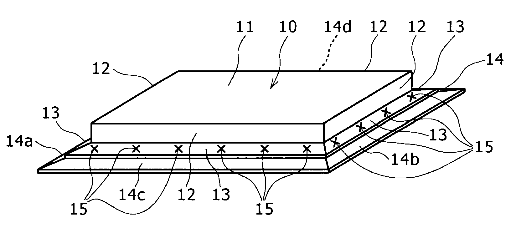
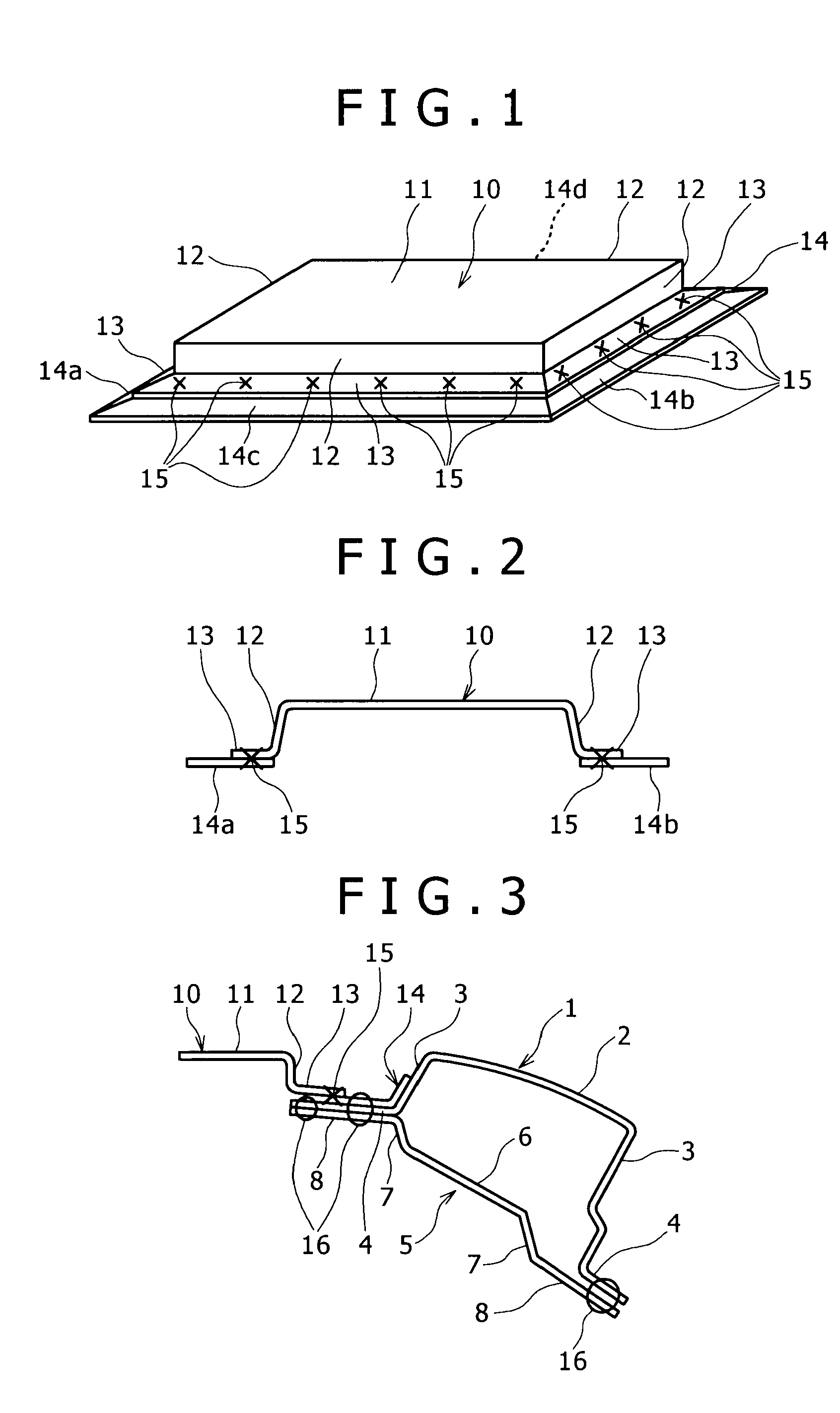
[0064]FIGS. 1 and 2 are a perspective view and a longitudinal cross-sectional view respectively showing an aluminum alloy panel as a second structural member of the invention, which is intended as a roof or the like set on the upper side of the vehicle body. FIG. 3 is a longitudinal cross-sectional view of one embodiment of a structural member of different materials obtained by bonding the aluminum alloy panel to a steel panel (steel panel structural member) serving as the first structural member, such as a roof side rail.

(Aluminum Alloy Panel)

[0065]In FIGS. 1 and 2, an aluminum alloy panel 10 is produced by press-molding an aluminum alloy sheet (rolled sheet) with a view to form a structural member, such as a roof. In the press-molding, the aluminum alloy panel 10 has its section formed in a substantially HAT (hat)-type shape which is a necessary shape as the structural member, corresponding to a desi...


PUM


Abstract

The invention provides a structural member of different materials having no different-material-bonded part between aluminum alloy material and steel material to be assembled. The structural member of different materials comprised of steel and aluminum alloy includes a first structural member including steel, and a second structural member having a part including steel and a part including aluminum alloy, the part including steel and the part including aluminum alloy being bonded by different-material bonding. The first structural member and the second structural member are bonded together only by bonding of steels between the part including steel of the second structural member and the first structural member.

Description

TECHNICAL FIELD[0001]The present invention relates to a structural member of different materials which includes a combination of an aluminum alloy material and a steel material. The term aluminum alloy panel or steel panel as used in the present specification includes not only a single plate panel, but also a panel structural member (panel structure) composed of an outer panel and an inner panel. Therefore, the term structural member of different materials as used in the present invention may respectively include a combination of single plate panels of an aluminum alloy panel and a steel panel, a combination of panel structural members, and a combination of a single plate panel and a panel structural member.[0002]The structural member of different materials in the invention has no or a small area of a different-material-bonded part between the aluminum alloy material and the steel material to be assembled. Thus, the structural member of the invention is suitably applied to a structu...

Claims


Application Information

Patent Timeline
IPC IPC(8): B32B15/01B23K20/00
CPCB21J15/025B62D25/04B62D25/06Y10T428/12965B62D29/008Y10T428/12347Y10T428/12757B62D27/026
Inventor HASHIMURA, TORUFUKUMOTO, KOJITAKAHASHI, NAOTO
Owner KOBE STEEL LTD
Learn More