
Pillow panel reactor and process

Active Publication Date: 2010-04-15
EMERGING FUELS TECH
View PDF6 Cites 3 Cited by
  • Summary
  • Abstract
  • Description
  • Claims
  • Application Information

AI Technical Summary

Benefits of technology

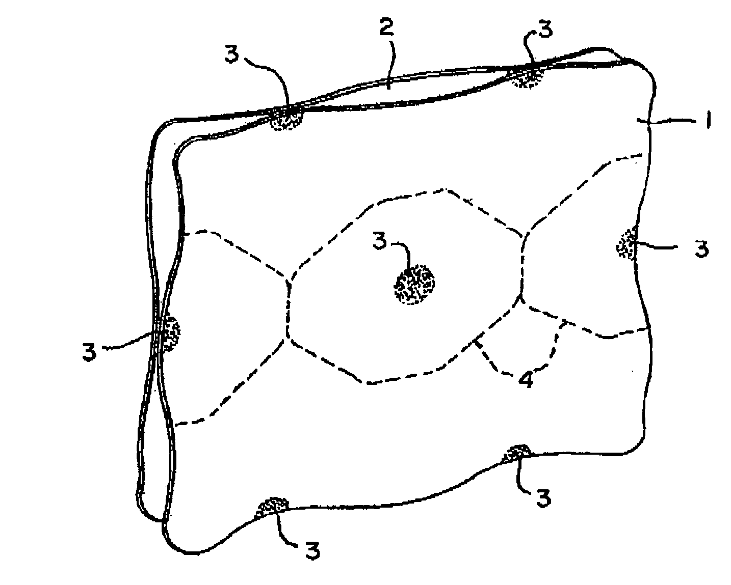
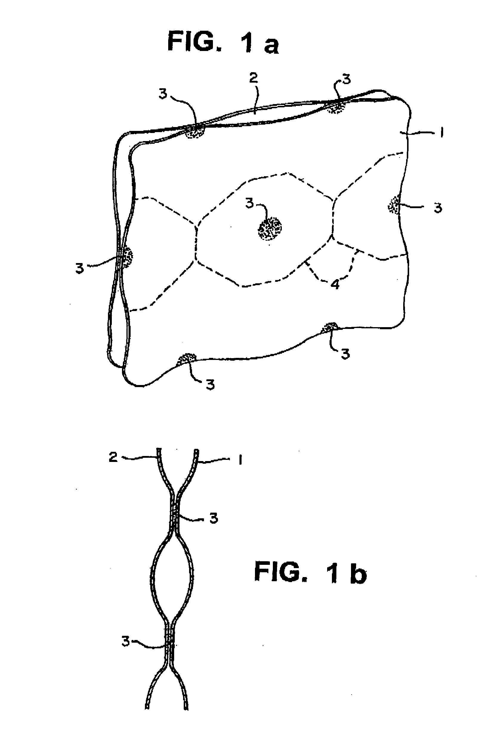
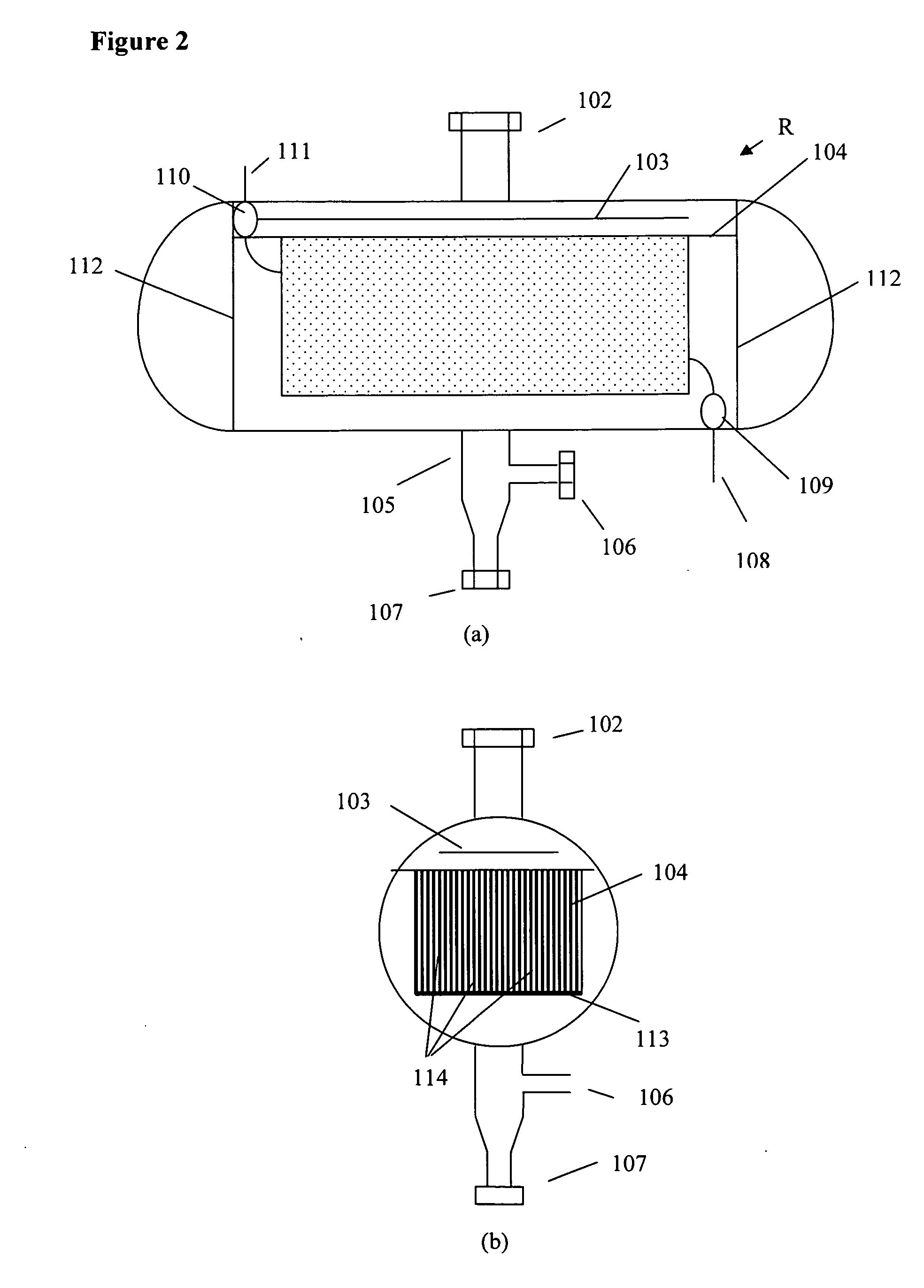
[0013]The present invention also relates to catalytic processes using a pillow panel reactor of the present invention wherein a catalyst suitable for the intended reaction is used. Non-limiting examples of catalytic processes that can take advantage of the present invention are preferably those that are endothermic as well as exothermic and that require the transfer of a significant amount of heat. One such reaction is the conversion of a gas comprising CO and H2 with or without inert components, such as N2, CO2 or methane into hydrocarbons. The present invention also relates to conducting a syngas conversion process in a reactor comprising a bundle of pillow panels for removal of reaction heat. The space between the panels is filled with catalyst particles.

Problems solved by technology

Additionally, the Fischer-Tropsch reaction is diffusion limited when the catalyst particle size is greater than about 300 microns.
The use of larger particles leads to diminished productivity and higher methane selectivity, thereby requiring higher catalyst volumes and diminished production of the higher valued C8+ hydrocarbons.
The reactor capacity may be limited due to heat and / or mass transfer problems.
However, the internal section of the reactor was of a much more complex design.
Lamella reactors had several drawbacks, for example they were mechanically complex and had poor heat transfer.
Although the catalyst was well distributed and close to a heat transfer surface or plates, however, the plates were just extended surfaces from the panels and the heat transfer was not very effective.
The poor heat removal limited the reactor capacity and led to local hot spots which caused catalyst damage.
Therefore, heat transfer was improved compared to that of the lamella reactor, but the capacity was still relatively low and the reactor was mechanically complex.
However, the tubes were long which limits catalyst particle size due to pressure drop and the large number of tubes requires a long time to load and unload the catalyst.
Such reactors, in spite of their very high performance, are difficult to construct and do not scale up well to large single train capacity.
Such reactors have difficulty with catalyst attrition, catalyst filtration and scale up.
However the slurry reactor is both costly and difficult to scale

Method used


Image

  • Pillow panel reactor and process
  • Pillow panel reactor and process
  • Pillow panel reactor and process

Examples


example 1

[0061]A 1 mm tri-lobe extrudate was prepared using 62.97 grams of Pural 100 alumina, 0.04 g 1:100 HNO3: distilled water solution, and 46 grams distilled water. The paste was worked for 10 minutes. The paste was then extruded with a laboratory extruder using a 1 mm tri-lobe die. The extrudate was dried for 12 hours at 120° C. and then ramped to 750° C. and calcined for 4 hours. 10 grams of the above extrudate was used to prepare a 20% Cobalt and 0.1% Ruthenium catalyst. A 15% Cobalt Nitrate solution was used to impregnate the support in 2 passes with 2 hours drying at 120° C. and 2 hours ramp to 300° C. with a 2 hour hold between passes. Ruthenium was added in the 2nd pass only prior to drying and calcination. An additional 10% Cobalt was added with 2 more passes of Cobalt Nitrate solution, each followed by the same calcination procedure described above. The resulting catalyst has 30% Cobalt and 0.1% Ruthenium. The catalyst is referred to as catalyst 1 in the table 1 below.

example 2

[0062]A 1 mm tri-lobe extrudate was prepared as in example 1. This extrudate was crushed and sieved to a particle size of 250-425μ. A 13.2 g sample of the crushed and sieved support was used to prepare a 30% Cobalt and 0.1% Ruthenium catalyst. A 15% Cobalt Nitrate solution was used to impregnate the support in 4 passes with a 2 hour drying step at 120° C. and a 2 hour ramp to 300° C. followed by a 2 hour hold for each pass. The Ruthenium was added in the 4th pass only prior to drying and calcination. This catalyst is identified as catalyst 2 in table 1 below.

TABLE 1Catalytic performance of catalysts 1 and 2.Conver-C1H2 / sionselectivityC5+ProductivityCO feedGHSVCatalyst 164.115.176.64121.82750Catalyst 264.96.287.27491.84750*All data at 400° F., 400 psig

example 3

[0063]A 110 cc sample of catalyst support crushed and sieved to 250-425 u was loaded into a 0.5 inch i.d. tubular reactor for pressure drop measurement. The catalyst zone was 3 ft in length. A representative syngas with a 2 / 1H2:CO ratio was passed over the catalyst support at various flow rates and pressure drop measurements were taken and are recorded in table 2 below. An Ergon equation was used to calculate some of the pressure drops for comparison and to calculate pressure drop at higher velocity than was measured. The highest flow (1800 sccm) for the calculated pressure drop is 0.52 ft / s.

TABLE 2FlowPress drop-PSIPress drop-PSI(sccm)(measured)(calculated)18652.929094.638836.46.448808.059009.411.869189.91450022.21800028.9


PUM

PropertyMeasurementUnit
Lengthaaaaaaaaaa
Heightaaaaaaaaaa
Temperatureaaaaaaaaaa

Abstract

A novel catalytic reactor suitable for use in chemical and petrochemical processes. The reactor is of a pillow panel that has superior heat transfer properties. This invention also relates to a chemical process, such as a Fischer-Tropsch synthesis process performed with use of the novel pillow panel reactor.

Description

CROSS-REFERENCE TO RELATED APPLICATIONS[0001]This application is based on Provisional Application U.S. Ser. No. 61 / 084,448 filed Jul. 29, 2008.FIELD OF THE INVENTION[0002]This invention relates to a novel catalytic reactor suitable for use in chemical and petrochemical processes. The reactor is of a pillow panel reactor that has superior heat transfer properties. This invention also relates to chemical processes, such as a Fischer-Tropsch synthesis process, conducted with use of this novel pillow panel reactor.BACKGROUND OF THE INVENTION[0003]Various endothermic and exothermic chemical reactions require effective heat transfer to maintain the reaction, especially in a commercial process unit, such as in a chemical plant or petroleum refinery where great amounts of heat need to be transferred. One such commercial chemical process that requires effective heat transfer is the Fischer-Tropsch synthesis process. Synthesis gas, a preferred feedstream to the reactor of this invention, is p...

Claims


Application Information

Patent Timeline
IPC IPC(8): C07C27/06B01J8/02C07C29/00C01C1/02C07C1/02
CPCB01J8/0221B01J19/249B01J2208/0015B01J2208/00814B01J2208/022B01J2219/00038C10G49/002B01J2219/1943B01J2219/2459B01J2219/2462B01J2219/2481B01J2219/2485C10G2/341B01J2219/182
Inventor ESPINOZA, RAFAEL
Owner EMERGING FUELS TECH
Learn More