Method for manufacturing a magneto-resistance effect element and magnetic recording and reproducing apparatus

a technology of magnetoresistance and effect elements, which is applied in the field of manufacturing methods of magnetoresistance effect elements and magnetic recording and reproducing apparatus, can solve the problems of reducing resistance, converting weak magnetic fields, and high resistance in tmr elements

Inactive Publication Date: 2010-04-15
TDK CORPARATION +1
View PDF115 Cites 11 Cited by
  • Summary
  • Abstract
  • Description
  • Claims
  • Application Information

AI Technical Summary

Benefits of technology

[0016]According to an aspect of the invention, there is provided a method for manufacturing a magneto-resistance effect element having a first magnetic layer including a ferromagnetic material, a second magnetic layer including a ferromagnetic material and a spacer layer provided between the first magnetic layer and the second magnetic layer, the spacer layer having an insulating layer and a conductive portion penetrating through the insulating layer, the method including: forming a film to be a base material of the spacer layer; performing a first treatment using a gas including at least one of oxygen molecules, oxygen atoms, oxygen ions, oxygen plasma and oxygen radicals on the film; and performing a second treatment using a gas including at least one of helium ions, helium plasma, helium radicals, neon ions, neon plasma and neon radicals on the film submitted to the first treatment.
[0017]According to another aspect of the invention, there is provided a magnetic recording and reproducing apparatus comprising: a magnetic head assembly including a suspension, a the magneto-resistance effect ele...

Problems solved by technology

However, when a head size becomes small with increasing of the recording density in a HDD, a heat or the like become problem and the TMR element, in which a sense current is flowed to the film in the direction perpendicular to the film surface thereof was put to practical use next.
However, the resistance in the TMR element is usually high because it uses a tunneling current through an insulating barrier.
It will become problem not to decrease the resistance of the element in future when the recording density is increased and the head size is downsized.
In a metallic CPP-GMR element in which the SV film is made of metallic films, the variation degree in resistance by the magnetization of the SV film becomes small so that to convert a weak magnetic field (for example, from a magnetic disk of high recording density) to an electric signal becomes difficult.
However, for achieving the MR variation ratio anticipated to be required in the future, further ingenuity is required.
These methods are not adequate to be applied to the configuration of the purpose of this invention, because the energy in all of these methods is so high that the base material is etched or a mixing occurs before the cutting the bonds.

Method used


Image

  • Method for manufacturing a magneto-resistance effect element and magnetic recording and reproducing apparatus
  • Method for manufacturing a magneto-resistance effect element and magnetic recording and reproducing apparatus
  • Method for manufacturing a magneto-resistance effect element and magnetic recording and reproducing apparatus

Examples


first embodiment

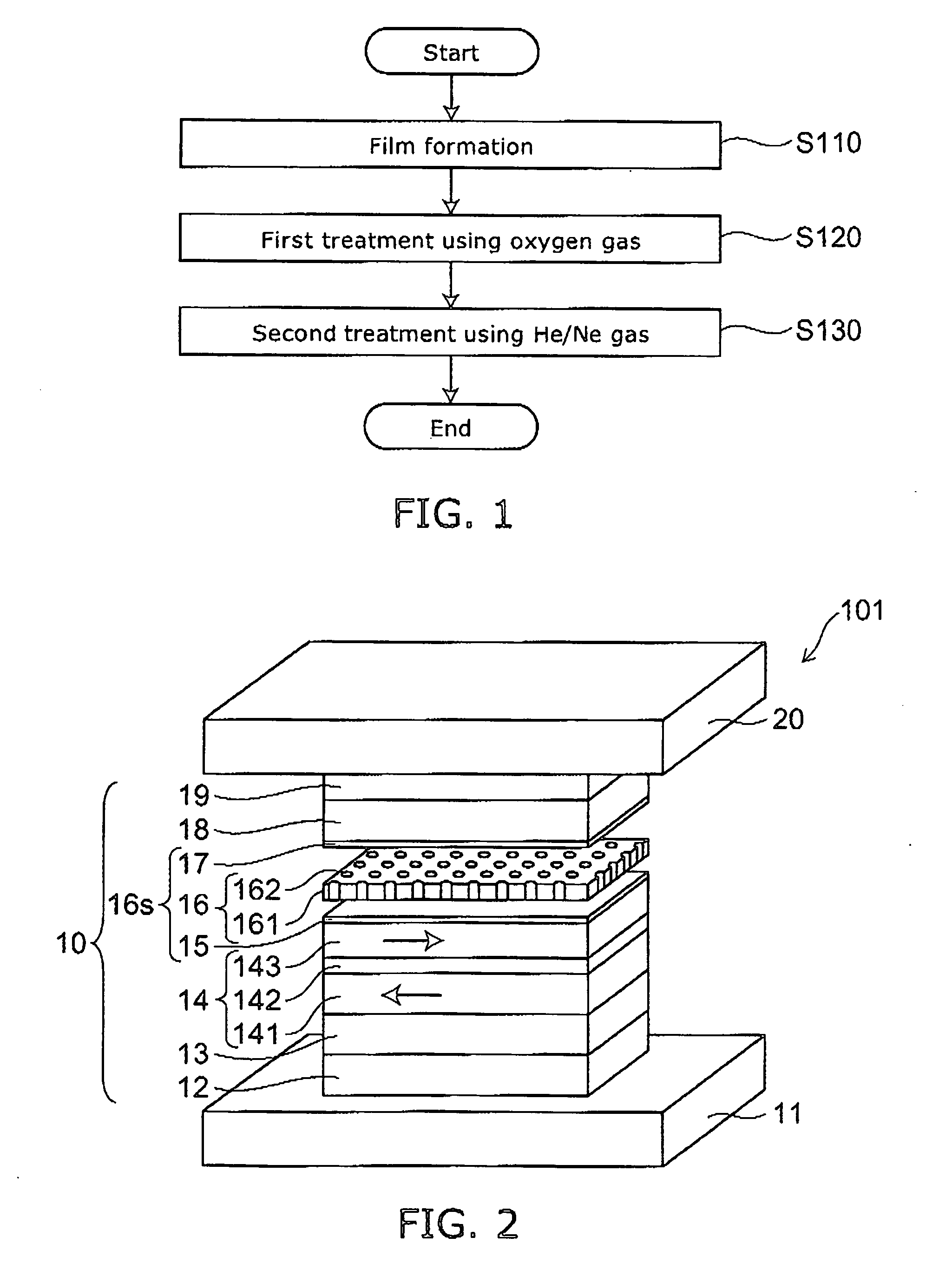
[0046]FIG. 1 is a flow chart illustrating a method for manufacturing a magneto-resistance effect element according to a first embodiment of this invention.

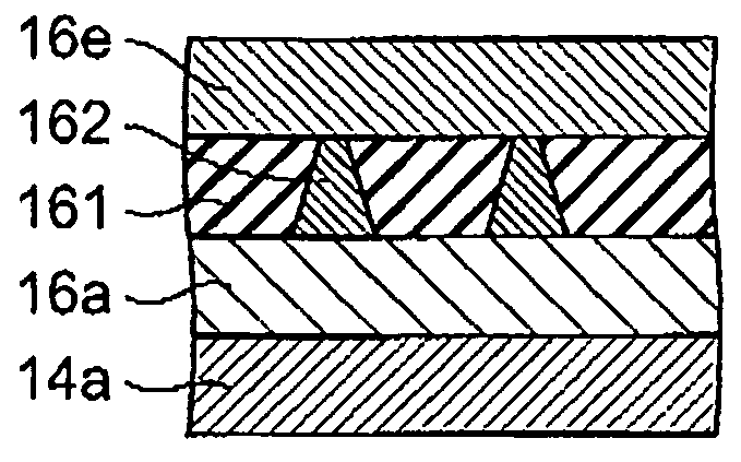
[0047]FIG. 2 is a schematic perspective view illustrating a configuration of a magneto-resistance effect element to which the method for manufacturing a magneto-resistance effect element according to a first embodiment of this invention is applied.

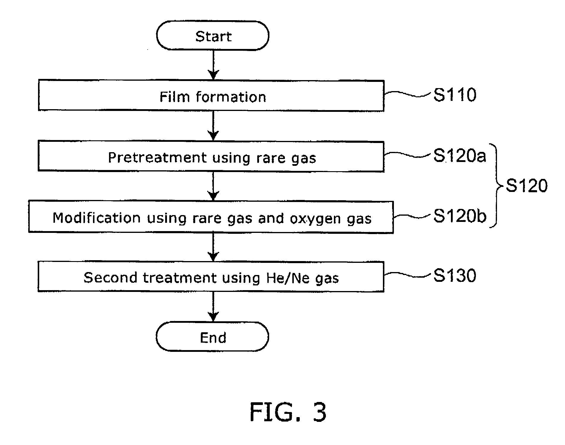
[0048]FIG. 3 is a flow chart illustrating a specific example of the method for manufacturing a magneto-resistance effect element according to a first embodiment of this invention.

[0049]FIGS. 4A to 4D are schematic sectional views following step sequence illustrating the method for manufacturing a magneto-resistance effect element according to a first embodiment of this invention.

[0050]That is, FIG. 4A represents the first step, and FIG. 4B represents the step following the step of FIG. 4A, and FIG. 4C represents the step following the step of FIG. 4B, and FIG. 4D represents the step foll...

second embodiment

[0190]FIG. 9 is a flow chart illustrating a method for manufacturing a magneto-resistance effect element according to a second embodiment of this invention.

[0191]As shown in FIG. 9, in the method for manufacturing a magneto-resistance effect element according to a second embodiment of this invention, after the first step (Step S110), the second step (Step S120) and the third step (Step S130), which are explained with respect to FIG. 1, further a fourth step (Step S140) is carried out.

[0192]Also in this step, the second step (Step S120) may include the PIT step (Step S120a illustrated in FIG. 3) and the IAO step (Step S120b illustrated in FIG. 3).

[0193]In the fourth step, the film submitted to the second treatment is submitted to the third treatment of at least any one of irradiation of ion of argon which is heavier rare gas than helium and neon, irradiation of argon plasma, and heating.

[0194]As the third treatment, the insulating layer 161 and the conductive portion 162 are submitte...

third embodiment

[0235]The magneto-resistance effect element 105 (not shown) according to a fourth embodiment of this invention is any one of the magneto-resistance effect elements (CCP elements) produced by the method for manufacturing a magneto-resistance effect element of the first and the second embodiments. That is, the magneto-resistance effect element 105 includes the above-described magneto-resistance effect elements 101 and 104.

[0236]In the embodiment of the present invention, in view of high density recording, the element resistance RA is set preferably to 500 mΩ / μm2 or below, more preferably to 300 mΩ / μm2 or below. In the calculation of the element resistance RA, the effective area A in current flow of the spin valve film is multiplied to the resistance R of the CPP-CPP element. Herein, the element resistance R can be directly measured, but attention should be paid to the effective area A because the effective area A depends on the element structure.

[0237]If the whole area of the spin val...


PUM

PropertyMeasurementUnit
Timeaaaaaaaaaa
Poweraaaaaaaaaa
Poweraaaaaaaaaa

Abstract

A method for manufacturing a magneto-resistance effect element is provided. The magneto-resistance effect element includes a first magnetic layer including a ferromagnetic material, a second magnetic layer including a ferromagnetic material and a spacer layer provided between the first magnetic layer and the second magnetic layer, the spacer layer having an insulating layer and a conductive portion penetrating through the insulating layer. The method includes: forming a film to be a base material of the spacer layer; performing a first treatment using a gas including at least one of oxygen molecules, oxygen atoms, oxygen ions, oxygen plasma and oxygen radicals on the film; and performing a second treatment using a gas including at least one of helium ions, helium plasma, helium radicals, neon ions, neon plasma and neon radicals on the film submitted to the first treatment.

Description

CROSS-REFERENCE TO RELATED APPLICATIONS[0001]This application is based upon and claims the benefit of priority from the prior Japanese Patent Application No. 2008-249237, filed on Sep. 26, 2008; the entire contents of which are incorporated herein by reference.BACKGROUND OF THE INVENTION[0002]1. Field of the Invention[0003]This invention relates to a method for manufacturing a magneto-resistance effect element and a magnetic recording and reproducing apparatus.[0004]2. Background Art[0005]Performance of a magnetic device, particularly such as a magnetic head is extremely enhanced by using Giant Magneto-Resistive Effect (GMR). Particularly, since a spin valve film (SV film) can exhibit a larger GMR effect, the SV film has developed the magnetic device such as a magnetic head and MRAM (Magnetic Random Access Memory).[0006]The “spin valve” film is laminated films having such a structure as sandwiching a non-magnetic metal spacer layer between two ferromagnetic layers and is called as s...

Claims


Application Information

Patent Timeline
IPC IPC(8): G11B5/33B05D5/12C23C16/513H05H1/24
CPCB82Y10/00B82Y25/00C23C8/36C23C14/081G11B2005/3996C23C14/5873G11B5/3163G11B5/3906C23C14/5833
Inventor YUASA, HIROMIFUKUZAWA, HIDEAKIFUJI, YOSHIHIKOMURAKAMI, SHUICHIHARA, MICHIKOZHANG, KUNLIANGLI, MINSCHRECK, ERHARD
Owner TDK CORPARATION
Why Eureka
Try Eureka