
Dual radiation detector

a detector and detector technology, applied in the field of radiation detectors, can solve the problems of deteriorating photopeak resolution, impractical passive collimation, and large probes for many intraoperative applications, and achieve the effect of increasing the total detection efficiency

Active Publication Date: 2010-04-15
UNIV OF WOLLONGONG
View PDF4 Cites 39 Cited by
  • Summary
  • Abstract
  • Description
  • Claims
  • Application Information

AI Technical Summary

Benefits of technology

[0022]Thus, because the scintillators are adjacent to their respective photodetectors (that is, without light pipe or other interconnecting means), it is unnecessary to employ any mediating light guide, and the apparatus can be made particularly compact and efficient. The output of the first photodetector can be used as the principal output channel of the apparatus; the output of the second photodetector can be used to gate the principal output (as is explained below) or, if resolution is less important, to increase total efficiency.
[0024]In one embodiment the apparatus includes an optical isolator located between the first and second scintillators. Such an isolator may not block all optical photons, but it nonetheless reduces the noise from various sources from being included in the output of the first photodetector.
[0027]Preferably the first and second photodetectors are coplanar and concentric. This arrangement allows the apparatus to be especially compact.
[0033]In one embodiment, the apparatus includes shielding (such as thin metal shielding) located around exposed portions of the second scintillator to prevent beta particles from interacting with the second scintillator. This embodiment allows beta particles to interact with the first scintillator and hence be detected; any gamma or X-ray background detected via interaction with the first scintillator can be subtracted according to the level of gamma or X-ray background events detected via the second scintillator, which is particularly useful in high gamma or X-ray background environments.
[0049]The method may include generating a principal output comprising or derived from the first output signal, and either gating the principal output with the second output signal or increasing total detection efficiency with the second output signal.

Problems solved by technology

Localization of radioactive sources with high gamma energies—such as PET isotopes (511 keV)—using passive collimation is impractical owing to the thick collimator wall of such probes, which make the probes too bulky for many intraoperative applications.
The disadvantage of this approach—whether using a single or dual scintillator detectors—is that photopeak resolution deteriorates owing to the coupling of the fibre optic light pipe and the photomultiplier.
This is due to loss of photons and hence deterioration in the spatial resolution of the probe.
However, this probe has limitations for large tumours determinations, in addition to the aforementioned disadvantages in the coupling of scintillators to photomultipliers with light pipes.
However, gamma background activity from other parts of the body remains a problem for the accurate detection of beta particles on a gamma background.
However, they do not allow such probes to be used as efficient gamma probes in spectroscopy mode.
While the detector module is small, the disadvantages of such a probe arise from the complicated mounting of detector and read out electronics and its inutility as a gamma spectroscopy intraoperative probe for high energy gamma isotopes, such as Tc-99m.
The identification of the signature of radioactive isotopes with medium and low energy gamma photons can be difficult in the presence of high energy masking gamma isotopes, as the monitored events may be statistically poor compared with the Compton scattering background from higher energy masking isotopes.
Such events produce no usable signal for spectroscopy purposes.
This results in the suppression of the Compton continuum in the primary detector spectrum and hence to a greater probability of detection of lower energy gamma photons otherwise statistically lost in the Compton background.
This is inconvenient, requiring both photomultipliers and solid state detector readout electronics as well as different high voltage biasing circuitry.
It also leads to a large volume of inactive material, a so-called “dead layer,” between the primary and veto detectors that reduces Compton suppression efficiency.

Method used


Image

  • Dual radiation detector
  • Dual radiation detector
  • Dual radiation detector

Examples


Embodiment Construction

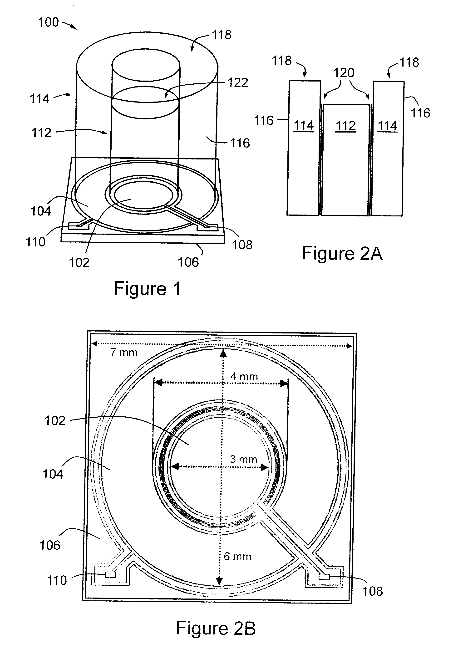
[0073]FIG. 1 is a perspective, schematic view of a detector module 100 comprising dual concentric Si planar photodiodes on a single Si wafer directly optically coupled to dual optically isolated high Z scintillators, and so referred to below as Dual Photodiode Dual Scintillator (DPDS) detector module 100. Thus, referring to FIG. 1, DPDS detector module 100 comprises a generally circular, inner Si planar photodiode 102 and a generally annular, outer Si planar photodiode 104 (both p-n junctions are P+ doped), located concentrically upon an N+ doped Si wafer substrate or base 106. Photodiodes 102, 104 are in fact produced on the Si base 106, which makes them particularly convenient to manufacture, especially in compact form. The photodiodes 102, 104 are of approximately 0.5 mm thickness, and have respective contact pads 108, 110. Above the photodiodes 102, 104 (hence opposite base 106) and directly coupled thereto are two corresponding high Z scintillators: inner scintillator 112 and o...


PUM


Abstract

A radiation detection apparatus and method, the apparatus (100) comprising a first scintillator (112) for interacting with radiation and outputting light in response thereto, a first photodetector (102) adjacent to the first scintillator (112) for receiving and detecting light from the first scintillator (112) and outputting (108) a first output signal in response thereto, a second scintillator (114) located around the first scintillator (112), for interacting with radiation and outputting light in response thereto, and a second photodetector (104) adjacent to the second scintillator (114) for receiving and detecting light from the second scintillator (114) and outputting (110) a second output signal in response thereto.

Description

RELATED APPLICATION[0001]This application is based on and claims the benefit of the filing date of AU application no. 2007900655 filed 9 Feb. 2007, the content of which as filed is incorporated herein by reference in its entirety.FIELD OF THE INVENTION[0002]The present invention relates most particularly to a radiation detector with dual photodetectors and either a single or dual scintillators, and to a radiation probe based on such a detector.BACKGROUND OF THE INVENTION[0003]In the surgical treatment of cancer, and particularly in the treatment of breast cancer, the extend of intervention (e.g. mastectomy or ‘lumpectomy’) constitutes an important decision. The status of the lymph nodes—ascertained by biopsy during surgery—is a particularly important factor in the making of that decision. The sentinel lymph node (SN) is an important indicator of the spreading of the cancer cells from the primary tumour through the lymphatic system. To localize the SN with high accuracy intra-operati...

Claims


Application Information

Patent Timeline
IPC IPC(8): G01T1/20
CPCG01T1/161A61B6/4258G01T1/20
Inventor LERCH, MICHAEL LLOYD FRANZROZENFELD, ANATOLYGEKTIN, OLEXANDER
Owner UNIV OF WOLLONGONG
Learn More