
Non-aqueous electrolyte secondary battery, electrode used for secondary battery, and method of manufacturing electrode

a technology of non-aqueous electrolyte and secondary batteries, which is applied in the direction of cell components, final product manufacturing, sustainable manufacturing/processing, etc., can solve the problems of low mechanical strength of the tab, electrode strain, and rapid reduction of the battery capacity from the normal level, so as to prevent the capacity from being reduced, reduce defects, and high power

Active Publication Date: 2010-04-01
KK TOSHIBA
View PDF2 Cites 49 Cited by
  • Summary
  • Abstract
  • Description
  • Claims
  • Application Information

AI Technical Summary

Benefits of technology

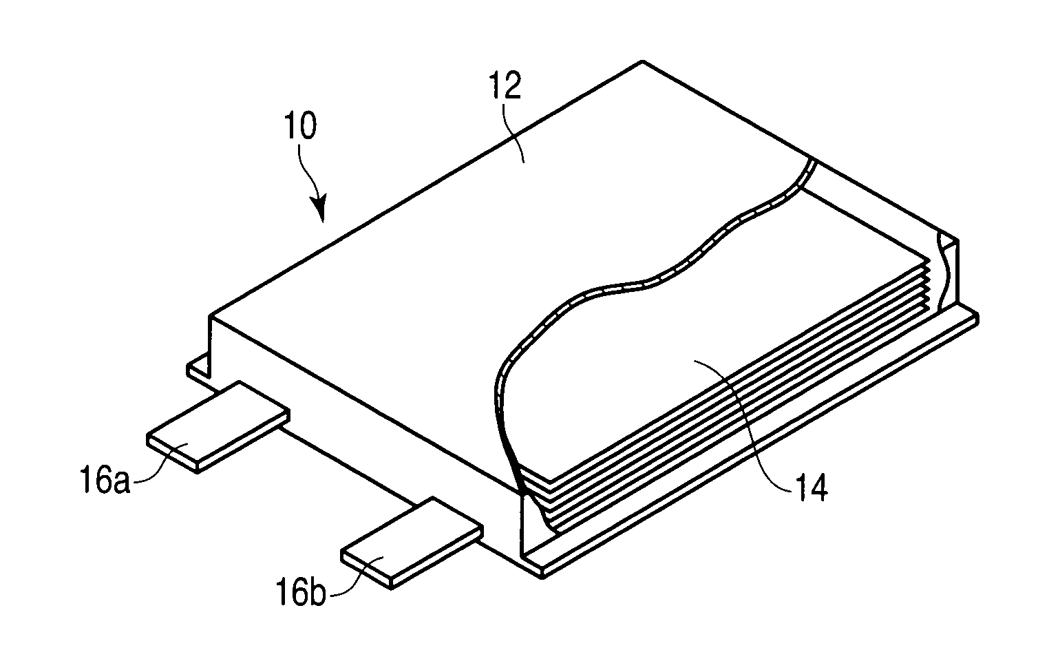
[0014]The present invention has been contrived in consideration of these circumstances, and an object thereof is to provide a non-aqueous electrolyte secondary battery capable of preventing the capacity from being reduced by a minute internal short circuit. Another object of the present invention is to provide a battery electrode and a method of manufacturing the battery electrode, capable of reducing defects due to bending of tabs.
[0018]According to an aspect of the present invention, it is possible to obtain a non-aqueous electrolyte secondary battery capable of preventing the capacity from being reduced by a minute short circuit, and outputting high power. According to an embodiment of the present invention, it is possible to provide a battery electrode and manufacturing method thereof capable of reducing defects due to bending of tabs.

Problems solved by technology

However, at this time, the following problems are caused.
One of them is a problem due to the reduction in the resistance of the active material layer.
As a result of this, current leakage occurs even when the battery is not used, and the battery capacity is rapidly decreased from the normal level.
The second is a problem of electrode strain occurring in a coil-shaped electrode body formed by rolling up the electrodes into a cylinder or flat shape, when the electrode body is subjected to an electrode rolling / pressing process to reduce the resistance thereof.
However, in such a manufacturing method and electrode, a part on which no active material layer is arranged is located between the tab and the active material layer, and hence there is a problem to be solved in the capacity per unit volume.
Further, the mechanical strength of the tab is low, and hence a case is conceivable where the tab is deformed or strained in the manufacturing process.

Method used


Image

  • Non-aqueous electrolyte secondary battery, electrode used for secondary battery, and method of manufacturing electrode
  • Non-aqueous electrolyte secondary battery, electrode used for secondary battery, and method of manufacturing electrode
  • Non-aqueous electrolyte secondary battery, electrode used for secondary battery, and method of manufacturing electrode

Examples


first embodiment

[0126]FIGS. 9A, 9B, 10A, and 10B are schematic views showing an electrode to be used in a laminated electrode group, and a manufacturing step thereof.

[0127]As shown in FIGS. 9A and 9B, both surfaces of rectangular metallic foil excluding the circumferential edge part thereof are coated with slurry containing the active material, are thereafter dried, and are then pressed in the thickness direction of the coated part, whereby active material-coated parts (active material-containing layers) 2a and 2b are formed on both surfaces of the central part of the metallic foil 1. The part at which the metallic foil 1 is exposed, and which surrounds the active material-coated part 2a or 2b is an uncoated part 3.

[0128]As shown in FIG. 9B, the coating position of the active material-coated part 2a formed on one surface of the metallic foil 1 is deviated from the coating position of the active material-coated part 2b formed on the opposite surface of the metallic foil 1, and the deviation amount d...

second embodiment

[0135]FIGS. 11 and 12 are schematic views showing an electrode used in the rolled-up electrode group, and a manufacturing step thereof.

[0136]As shown in FIG. 11, both surfaces of the elongated belt-like metallic foil 1 excluding the both side edge parts in the longitudinal direction, and the one short side part are coated with slurry containing an active material, and thereafter the resultant is dried, whereby active material-coated parts (active material-containing layers) 2a and 2b are formed. A part at which the active material-coated parts 2a and 2b are not formed, and the metallic foil 1 is exposed is called an uncoated part 3. At the uncoated part 3a with a larger width of the two uncoated parts 3a and 3b positioned at both side edge parts of the metallic foil 1, a plurality of tabs 5 are formed in the cutting step to be described later.

[0137]The coating position of the active material-coated part 2a formed on the one surface of the metallic foil 1 is deviated from the coating...

third embodiment

[0143]In the first and second embodiments described previously, in the tab 5, the two sides Y opposed to each other may be inclined at an angle θ exceeding 90° toward the side edge (side parallel with the rolling direction) L of the electrode main body 4 as shown in FIG. 13. The tab 5 including such two sides Y has a trapezoidal shape, and a width of the proximal end part X thereof becomes larger than a width of the distal end thereof. Accordingly, it becomes possible to prevent the electrode from being cut with the joint part of the tab 5 being a starting point, and handle the electrode easily when the electrode is treated to manufacture the rolled-up electrode group. Further, each of both corner parts of the proximal end part of the tab is formed into a rounded shape. In this case, it is possible to further improve the strength of the tab 5.

[0144]The electrode 7 for the secondary battery described above can be applied to a non-aqueous electrolyte battery electrode.

[0145]As the met...


PUM

PropertyMeasurementUnit
Angleaaaaaaaaaa
Poweraaaaaaaaaa
Widthaaaaaaaaaa

Abstract

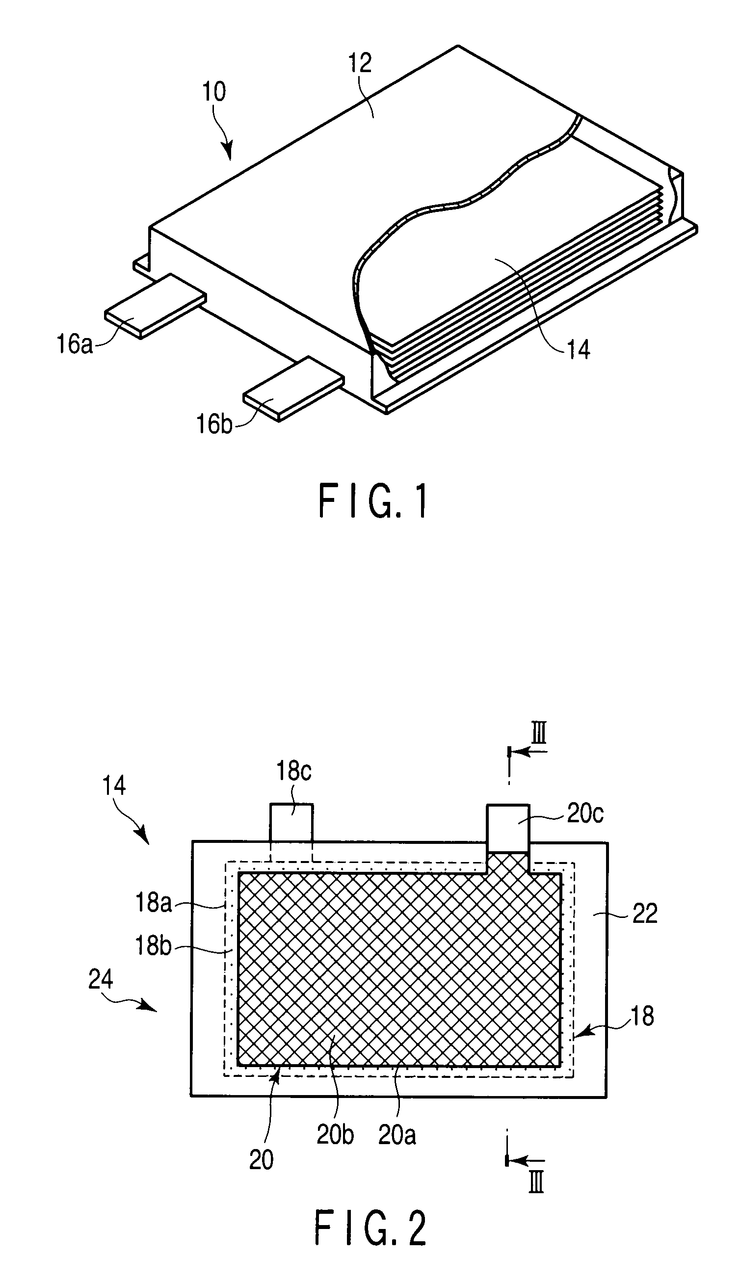
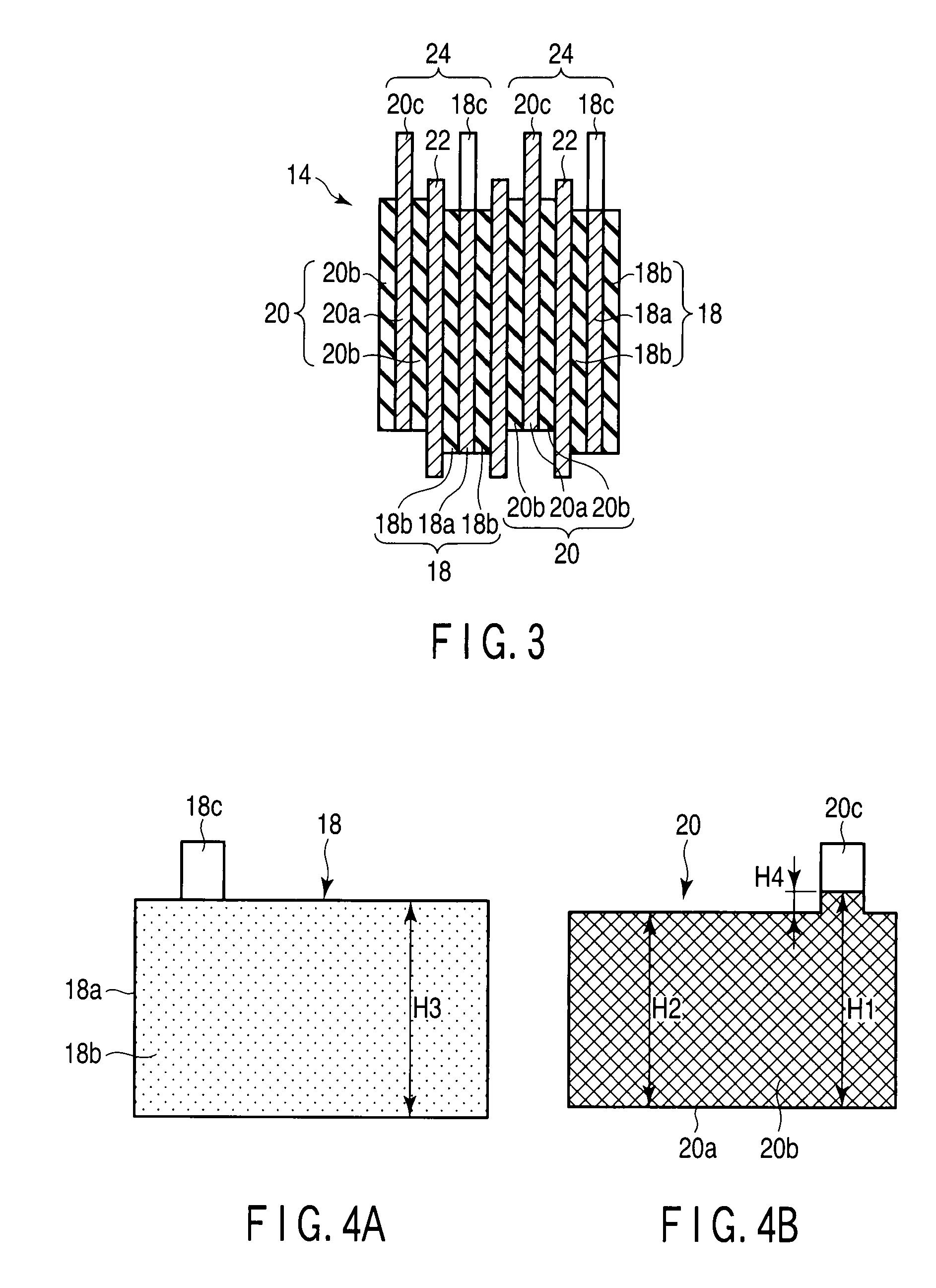
A non-aqueous electrolyte secondary battery includes an electrode body including a positive electrode and a negative electrode superimposed upon each other with a separator interposed therebetween. The negative electrode is superimposed upon the positive electrode in a state where a negative electrode active material layer, except the part on a proximal end part of a negative electrode tab, is positioned inside an outer edge of a positive electrode active material layer of the positive electrode. A width H1 of the negative electrode active material layer including the part on the proximal end part of the negative electrode tab, width H2 of the negative electrode active material layer or negative electrode current collector at a part other than the negative electrode tab, and width H3 of the positive electrode active material layer are formed to satisfy the relationships of H2<H3, and (H1−H2)≧(H3−H2)÷2.

Description

CROSS-REFERENCE TO RELATED APPLICATIONS[0001]This application is based upon and claims the benefit of priority from prior Japanese Patent Applications No. 2008-250231, filed Sep. 29, 2008; and No. 2008-255198, filed Sep. 30, 2008, the entire contents of both of which are incorporated herein by reference.BACKGROUND OF THE INVENTION[0002]1. Field of the Invention[0003]The present invention relates to a non-aqueous electrolyte secondary battery, an electrode used for the secondary battery, and a method of manufacturing the electrode.[0004]2. Description of the Related Art[0005]In recent years, a non-aqueous electrolyte secondary battery has attracted attention as a power source of a hybrid electric vehicle or electric storage device for an electric generator using green energy such as solar energy and wind power. In such uses, the temporal variation in the load or generated power is dramatic, and hence a secondary battery with high capability for instantly storing or releasing a large ...

Claims


Application Information

Patent Timeline
IPC IPC(8): H01M4/02B05D5/12H01M4/04H01M4/131H01M4/1391H01M4/485H01M4/58H01M10/0525H01M10/0585H01M10/0587H01M50/533H01M50/534H01M50/538H01M50/54
CPCH01M4/131Y10T29/49117H01M4/1391H01M4/139H01M10/0525Y02T10/7011Y10T29/49108H01M10/0422H01M4/661Y10T29/49115H01M10/0585H01M10/0587H01M2/263H01M2/266Y02E60/122H01M4/485Y02E60/10H01M50/538H01M50/54Y02P70/50H01M50/534H01M50/533Y02T10/70
Inventor MORISHIMA, HIDEAKIKOBAYASHI, TAKASHIHIKATA, SEIICHIKOBAYASHI, YOSHIKAZUOHSAKI, TAKAHISATOYOTA, NATSUKIISHII, HARUCHIKA
Owner KK TOSHIBA
Learn More