Handheld or vehicle-mounted platform stabilization system
- Summary
- Abstract
- Description
- Claims
- Application Information
AI Technical Summary
Benefits of technology
Problems solved by technology
Method used
Image
Examples
embodiment 20
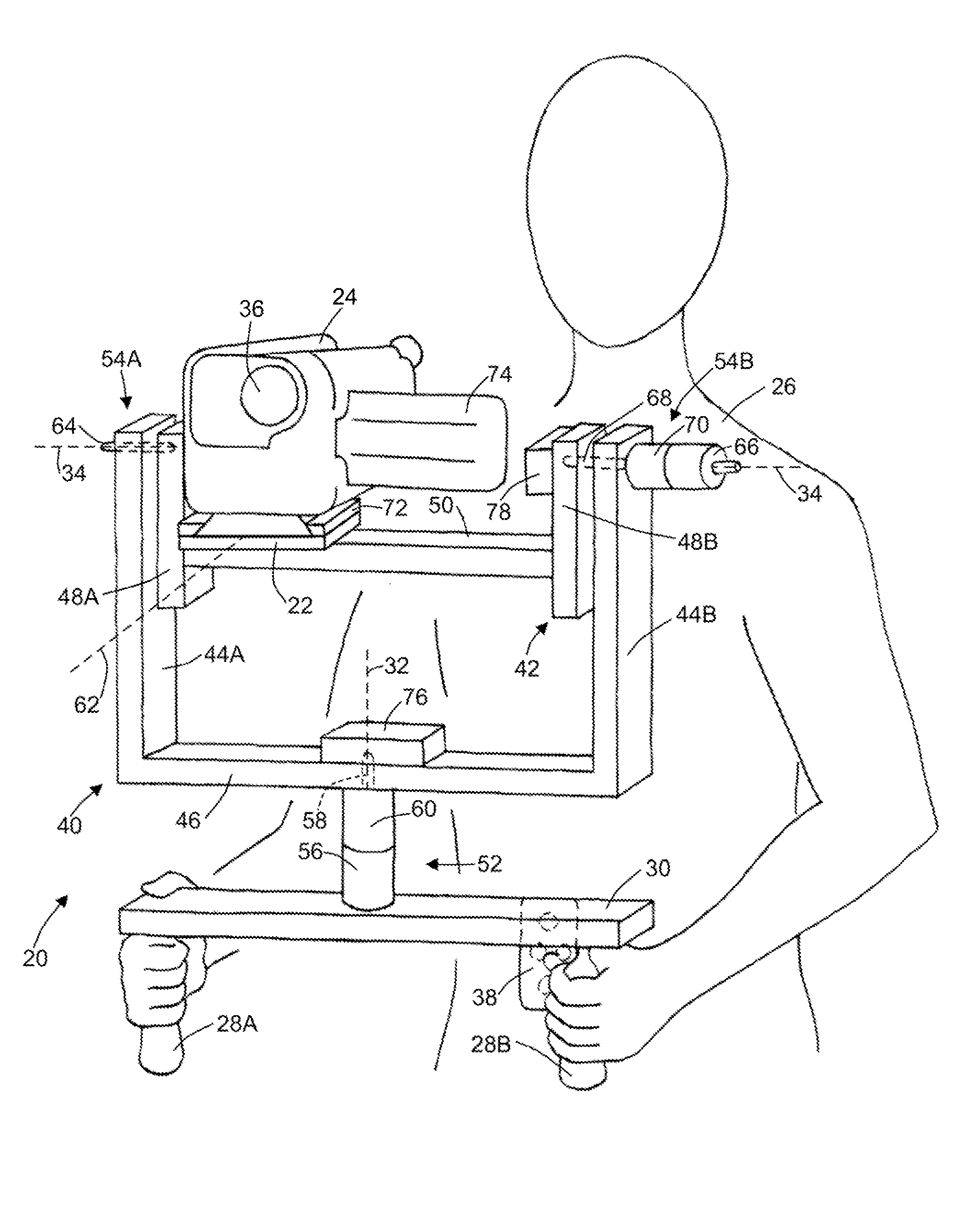
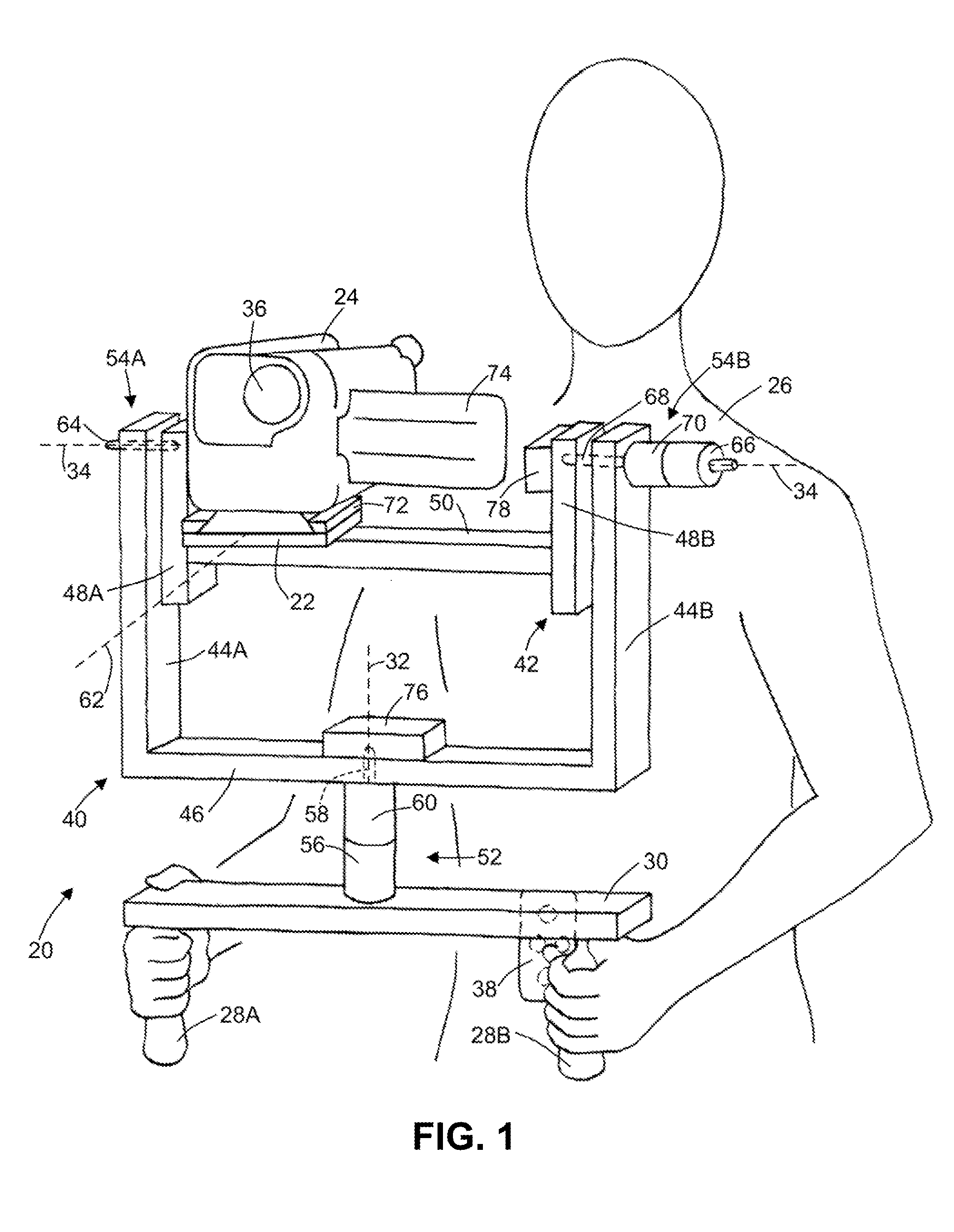
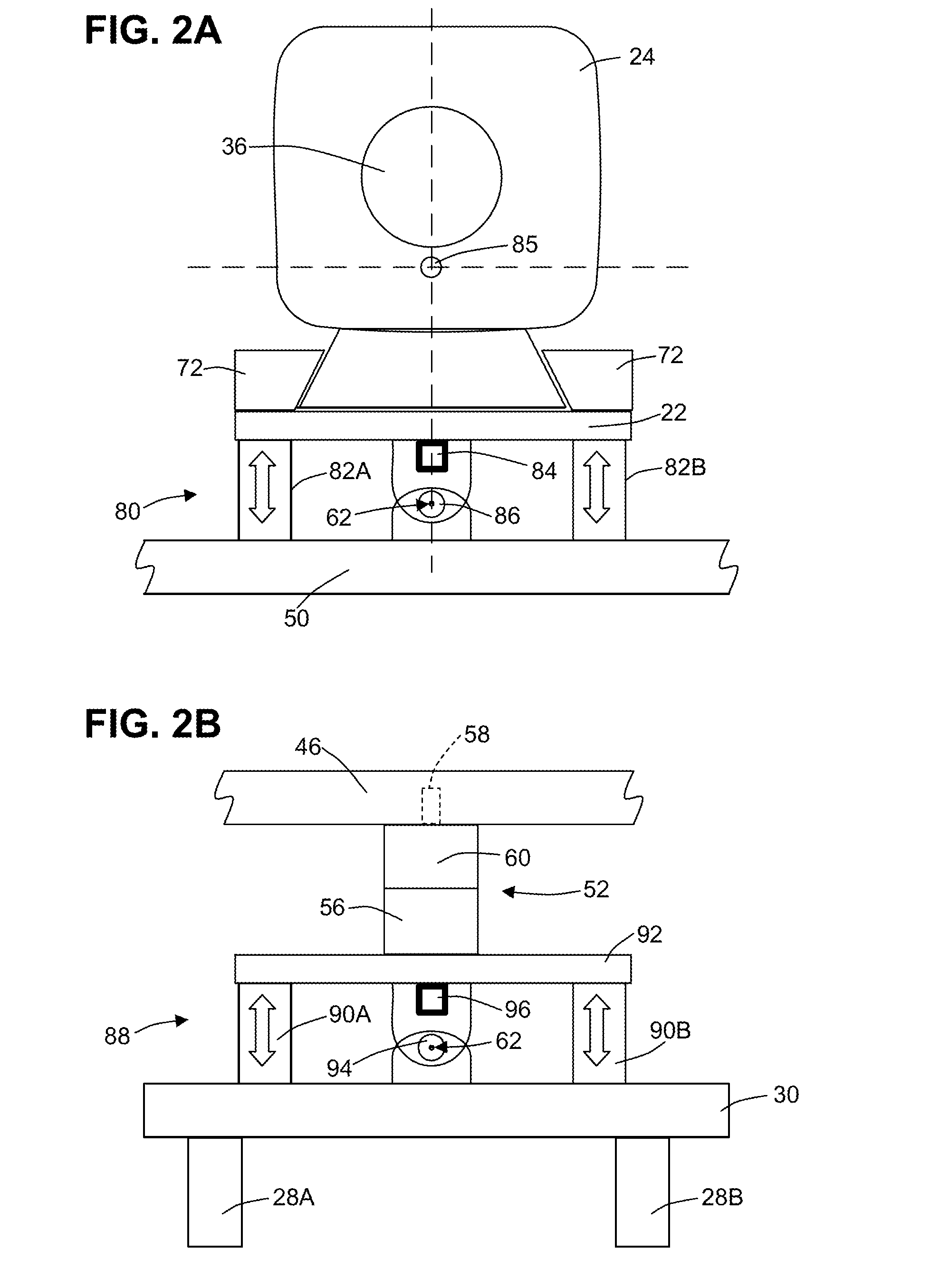
[0069]FIG. 1 illustrates an exemplary camera stabilization system embodiment 20 that stabilizes a platform 22 adapted to support and stabilize, e.g., a camera 24 against all yaw and pitch motion induced by the operator 26 through, e.g., a pair of handles 28A-B attached to a base 30. System 20 provides two orthogonal rotational degrees of freedom about a yaw axis 32 and a pitch axis 34. These degrees of freedom correspond respectively to panning and tilting of camera 24 at platform 22, which together define a center of mass (not shown), also herein denominated centroid or mass centroid. FIG. 1 depicts camera 24 with the camera lens 36 directed generally level and forward. However, system 20 allows panning and / or tilting of camera 24 through a range of over 180 degrees with full stabilization at any orientation. For example, camera lens 36 may be tilted to face vertically upward or nearly vertically downward and may be panned from side to side and around to the rear on either side. As...
embodiment 102
[0089]FIG. 3B is a close-up front view of an alternative pivot assembly embodiment 102 showing the actuator 104 with a rigidly-coupled rotation sensor 106 having a rotation-sensitive sensor axis 108 that is close to but not coincident to the axis of rotation 110 of the pivot motor shaft 112. Preferably, to most accurately determine the true rotational motion of the stabilized platform, rotational sensors should be disposed as close to the associated rotational axis as possible. Especially for gyro sensors that are not completely insensitive to translational motion, the gyro sensor should be disposed close to the associated rotation axis to minimize tangential motion effects at the gyro sensor output and be less sensitive to flexing of the rotationally supported frame
embodiment 114
[0090]FIG. 3C is a close-up front view of another alternative pivot assembly embodiment 114 showing actuator 116 with a rigidly-coupled yaw rotation sensor 118 that is raised by the rigid sensor support 120 above the mounting surface in the direction of the rotation-sensitive sensor axis 122, which is coincident to the axis of rotation of the pivot motor shaft 124. It may be readily appreciated that the teachings of FIGS. 3B and 3C apply to any stabilized axis.
[0091]Because the handheld system of this invention and its pitch and yaw frames must be lightweight, they are unavoidably flexible and will bend slightly as the actuators torque them to accelerate the relatively large inertial load of the stabilized camera platform. If the motion sensors are mounted directly to the stabilized camera stage, they must signal the spurious oscillations of the inertial camera stage mass resulting from the excitation of the complex spring-mass mechanical system. High control gains are ordinarily no...
PUM
 Abstract
Description
Claims
Application Information
 - R&D
- Intellectual Property
- Life Sciences
- Materials
- Tech Scout
- Unparalleled Data Quality
- Higher Quality Content
- 60% Fewer Hallucinations
Browse by: Latest US Patents, China's latest patents, Technical Efficacy Thesaurus, Application Domain, Technology Topic, Popular Technical Reports.
© 2025 PatSnap. All rights reserved.Legal|Privacy policy|Modern Slavery Act Transparency Statement|Sitemap|About US| Contact US: help@patsnap.com


