
Arrangement for and method of generating uniform distributed line pattern for imaging reader

a distribution pattern and imaging reader technology, applied in the field of distribution pattern generation and distribution pattern generation of imaging reader, can solve the problems of poor coupling efficiency between the led and the cylindrical lens, the use of the single large led and the single cylindrical lens is problematic, and achieves the effects of increasing light throughput, increasing light throughput, and being more visibl

Inactive Publication Date: 2010-04-01
SYMBOL TECH LLC
View PDF8 Cites 22 Cited by
  • Summary
  • Abstract
  • Description
  • Claims
  • Application Information

AI Technical Summary

Benefits of technology

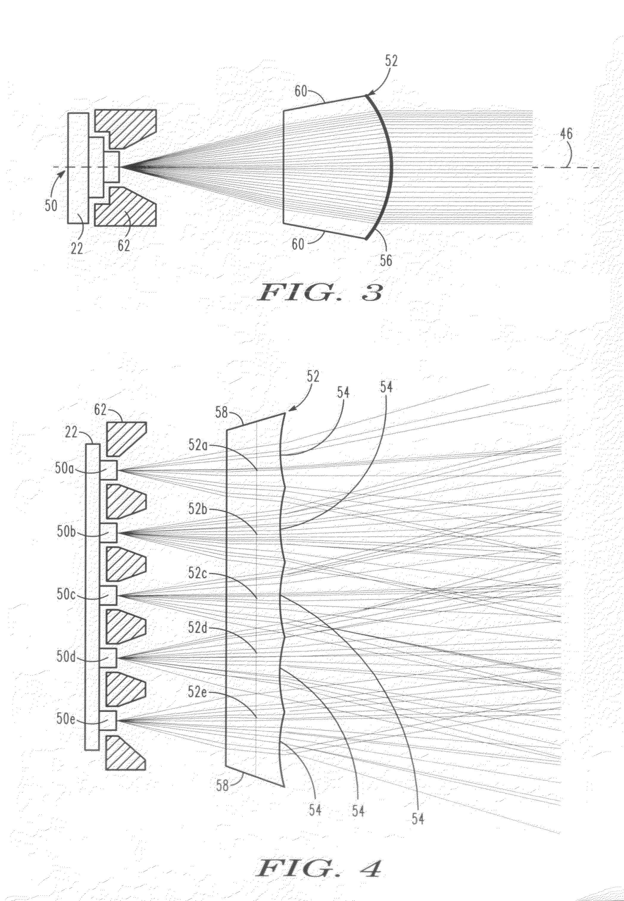
[0011]Each LED chip emits light, typically with a Lambertian intensity profile in which the intensity falls off along the horizontal direction as a function of the cosine angle. Hence, the LED chips are preferably spaced apart such that their intensity profiles overlap, thereby creating a more uniform intensity distribution along the horizontal direction. Since light emitted by one chip could interfere with light emitted by an adjacent chip, a baffle is preferably located between adjacent LED chips for resisting optical crosstalk that would otherwise corrupt the uniformity of the distributed line pattern. The baffles could also serve as an alignment aid when positioning the linear lens array relative to the light source.
[0012]One additional feature of the present invention resides in first coupling the LED chips to dome-shaped field lenses to reduce the conical angle of the emitted light prior to reaching the linear lens array. This feature will increase the light throughput. The LED chips could also be coupled to an array of parabolic reflective concentrators, again to constrain the conical angle and to increase the light throughput. The concentrators could also serve as the aforementioned baffles.
[0013]Yet another feature of the present invention resides in configuring the LED chips to emit light of different colors. For example, one group of the chips could emit green light which is more visible to a human eye, and thus is especially useful when the distributed line pattern is used as an aiming pattern; and another group of the chips could emit red light which is more visible to the imager due to increased sensitivity to red light, and thus is especially useful when the distributed line pattern is used as an illuminating pattern.
[0015]In accordance with this invention, the compound curvature lenses form the distributed line pattern as wide and short with sharp edges and as not dominated by optical aberrations. The intensity of the distributed line pattern is uniform with much less fall off away from the axis at opposite end regions of the distributed line pattern. Also, the coupling efficiency between the elongated light source and the elongated linear lens array is much improved, thereby increasing light throughput and enhancing reading performance.

Problems solved by technology

Although generally satisfactory for its intended purpose, the use of the single large LED and the single cylindrical lens has been problematic, because the distributed line pattern typically has a height taller than that desired, does not have sharp edges, is dominated by optical aberrations, and is nonuniform in intensity since the light intensity is brightest along an optical axis on which the LED is centered, and then falls off away from the axis, especially at opposite end regions of the distributed line pattern.
Also, the coupling efficiency between the LED and the cylindrical lens has been poor.
Adding an aperture stop between the LED and the cylindrical lens will improve the sharpness (i.e., shorten the height) of the distributed line pattern, but at the cost of a poorer coupling efficiency and a dimmer distributed line pattern that, of Course, degrades reading performance.
In addition, the use of an imaging reader has been frustrated, because an operator cannot tell whether the imager, or the reader in which the imager is mounted, is aimed directly at the target symbol, which can be located anywhere within a range of working distances from the reader.

Method used


Image

  • Arrangement for and method of generating uniform distributed line pattern for imaging reader
  • Arrangement for and method of generating uniform distributed line pattern for imaging reader
  • Arrangement for and method of generating uniform distributed line pattern for imaging reader

Examples


Embodiment Construction

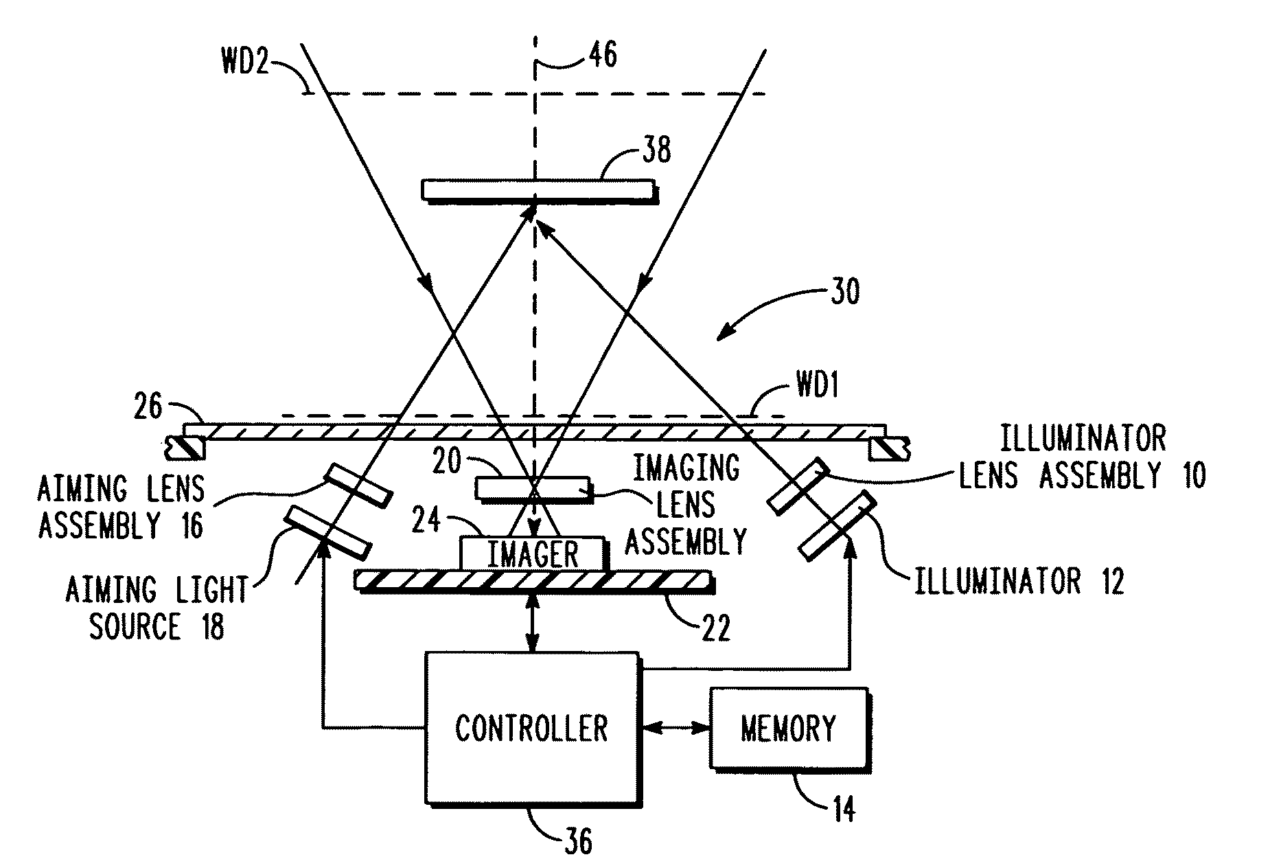
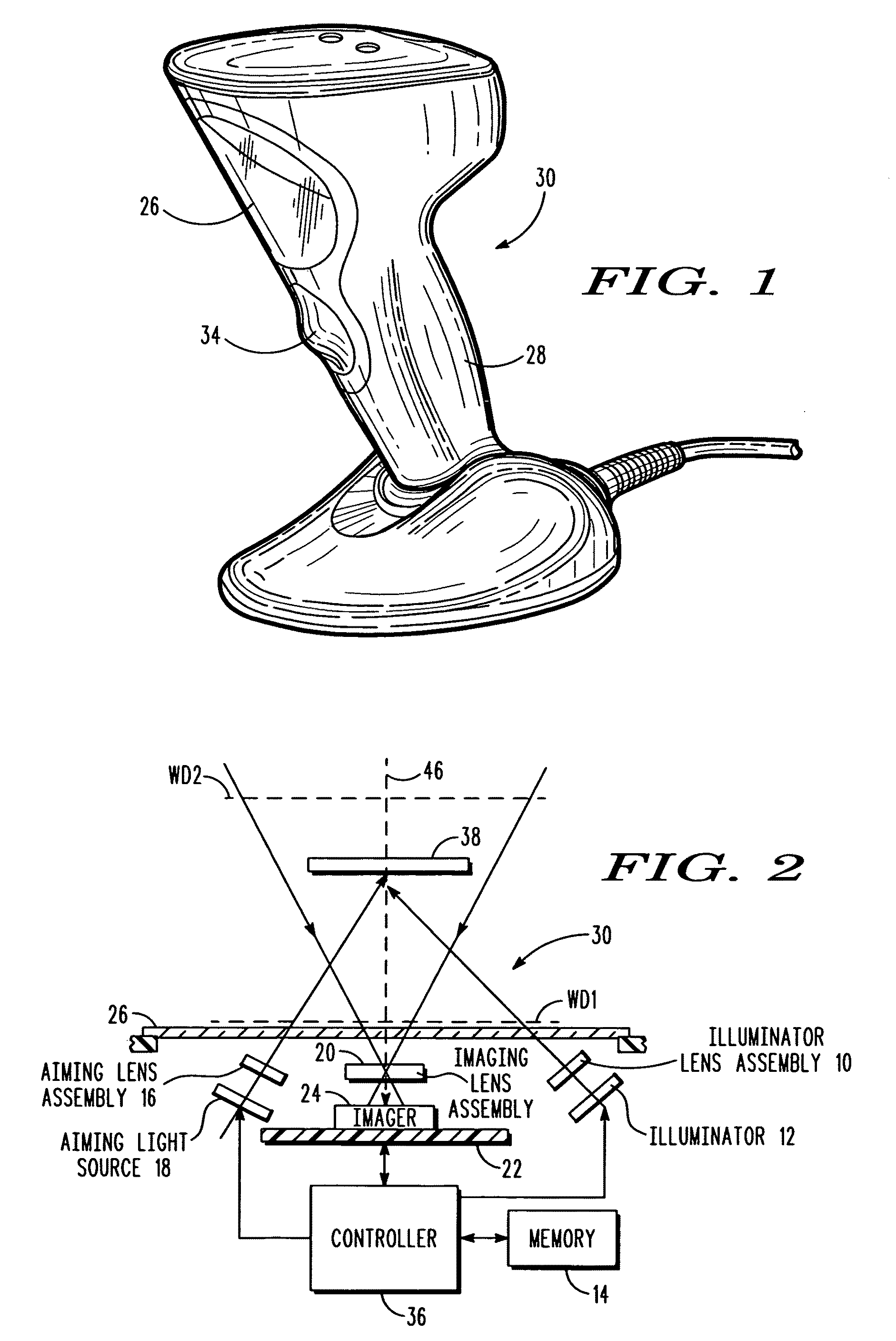
[0024]Reference numeral 30 in FIG. 1 generally identifies an imaging reader having a generally vertical window 26 and a gun-shaped housing 28 supported by a base 32 for supporting the imaging reader 30 on a countertop. The imaging reader 30 can thus be used in a hands-free mode as a stationary workstation in which products are slid, swiped past, or presented to, the vertical window 26, or can be picked up off the countertop and held in an operator's hand and used in a handheld mode in which a trigger 34 is manually depressed to initiate imaging of indicia, especially one-dimensional symbols, to be read at far distances from the window 26. In another variation, the base 32 can be omitted, and housings of other configurations can be employed. A cable, as illustrated in FIG. 1, connected to the base 32 can also be omitted, in which case, the reader 30 communicates with a remote host by a wireless link, and the reader is electrically powered by an on-board battery.

[0025]As schematically...


PUM


Abstract

A module and an arrangement for, as well as a method of, generating a generally uniform distributed line pattern of light on a symbol to be read by image capture employs a light source for generating light along an optical axis in a distribution having different extents along intersecting directions generally perpendicular to the axis, a linear lens array having a plurality of compound curvature lenses spaced apart from one another along one of said directions, for receiving the light from the light source, and for optically modifying the light from the light source to generate the generally uniform distributed line pattern of light on the symbol, each lens having a concave curvature for diverging the light along said one direction, and a convex curvature for collimating the light along the other of said directions, and a solid-state imager having an array of image sensors for capturing return light from the symbol over a field of view having different extents along the intersecting directions.

Description

DESCRIPTION OF THE RELATED ART[0001]Solid-state imaging systems or imaging readers, as well as moving laser beam readers or laser scanners, have both been used to electro-optically read targets, such as one-dimensional bar code symbols, particularly of the Universal Product Code (UPC) type, each having a row of bars and spaces spaced apart along one direction, as well as two-dimensional symbols, such as Code 49, which introduced the concept of vertically stacking a plurality of rows of bar and space patterns in a single symbol. The structure of Code 49 is described in U.S. Pat. No. 4,794,239. Another two-dimensional code structure for increasing the amount of data that can be represented or stored on a given amount of surface area is known as PDF417 and is described in U.S. Pat. No. 5,304,786.[0002]The imaging reader includes an imaging module having a solid-state imager with a sensor array of cells or photosensors, which correspond to image elements or pixels in a field of view of ...

Claims


Application Information

Patent Timeline
Patent Type & Authority Applications(United States)
IPC IPC(8): G06K7/10
CPCG06K7/10732G06K2207/1011G06K7/109G06K7/10831
Inventor LIU, RONGTSI-SHI, DAVIDYU, MING
Owner SYMBOL TECH LLC
Learn More