Asu nitrogen sweep gas in hydrogen separation membrane for production of hrsg duct burner fuel

a technology of duct burner fuel and hydrogen separation membrane, which is applied in the direction of separation processes, machines/engines, energy input, etc., can solve the problems of high cosub>2 /sub>sequestration cost and insufficient heat in the gas turbine exhaust to superheat the steam generated in the igcc process, so as to reduce h2 permeation partial pressure, reduce the effect of no production and increase the flux

Inactive Publication Date: 2010-04-01
PRAXAIR TECH INC
View PDF6 Cites 16 Cited by
  • Summary
  • Abstract
  • Description
  • Claims
  • Application Information

AI Technical Summary

Benefits of technology

[0009]In an IGCC plant that has CO2 capture, compressed ASU N2 is used as HTM permeate sweep to produce a fuel for the gas turbine combustor that will minimize NO production. In this invention, low pressure (LP) ASU N2 sweep is used in a second HTM to recover additional H2 and make near-atmospheric pressure fuel gas for firing in the HRSG duct burner. The use of ASU N2 sweep decreases H2 permeate partial pressure and increases flux while burning a H2—N2 fuel mixture in both the gas turbine and the duct burner helps to control NOx emissions. Also, increasing H2 recovery from the syngas decreases the amount of processing required to purify and sequester the CO2-rich membrane retentate, and firing a near-atmospheric pressure H2—N2 fuel mixture in the HRSG duct burner increases process efficiency. In an IGCC plant where electricity and H2 are both produced, burning a near-atmospheric pressure H2—N2 fuel mixture in the HRSG duct burner eliminates the need to supplementary fire depressurized syngas in order to superheat the steam for expansion in the steam turbine.

Problems solved by technology

In this scenario, the CO2 sequestration cost is high because Selexol®-type plants have high capital costs and the CO2 must be pressurized to greater than about 2000 psia from pressures as low as 18 psia.
While an IGCC plant with carbon capture that utilizes HTM technology may be cost competitive with plants that employ traditional carbon capture methods, there are several issues that may arise in these plant designs.
In addition, in an IGCC plant that produces both electricity and H2, there is often not enough heat in the gas turbine exhaust to superheat the steam that is generated in the IGCC process.

Method used


Image

  • Asu nitrogen sweep gas in hydrogen separation membrane for production of hrsg duct burner fuel
  • Asu nitrogen sweep gas in hydrogen separation membrane for production of hrsg duct burner fuel
  • Asu nitrogen sweep gas in hydrogen separation membrane for production of hrsg duct burner fuel

Examples


example 1

Power-Only IGCC Plant with CO2 Capture

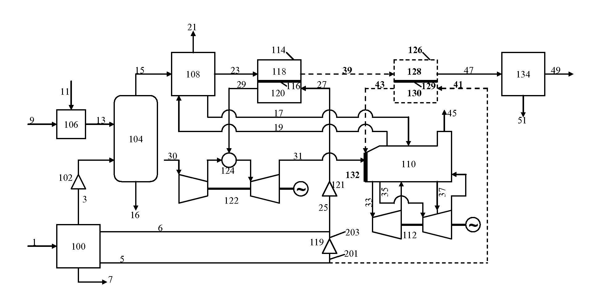
[0022]FIG. 1 shows a simplified process flow diagram (PFD) for an embodiment of the present invention in which a power-only (i.e. without high-purity H2 production) IGCC plant with CO2 capture utilizes HTM technology to make a H2—N2 fuel mixture for combustion in the gas turbine and the HRSG duct burner. The portions of the plant representing aspects of the present invention are drawn with dashed lines and / or labeled with bold font in the diagram. While not to be construed as limiting, an exemplary stream summary is given in Table 1 for the computer-simulated example case described below.

TABLE 1Stream summary for PFD shown in FIG. 1.Stream9315233947492943Flow (lbmol / hr)58092616038680212702053012700376801592Flow (kpph)268.1187.1526.5713.6678.6677.1546.3607.125.6Temp (F.)1971750750750100750750Pressure (psia)615500490485220037520H2 (%)32.047.34.10.61.045.645.6CO (%)39.91.32.42.50.50.00.0CO2 (%)11.029.954.456.395.30.00.0H2O (%)13.720.236.738.00.00.6...

example 2

Co-Production of H2 and Electrical Power in an IGCC Plant with CO2 Capture

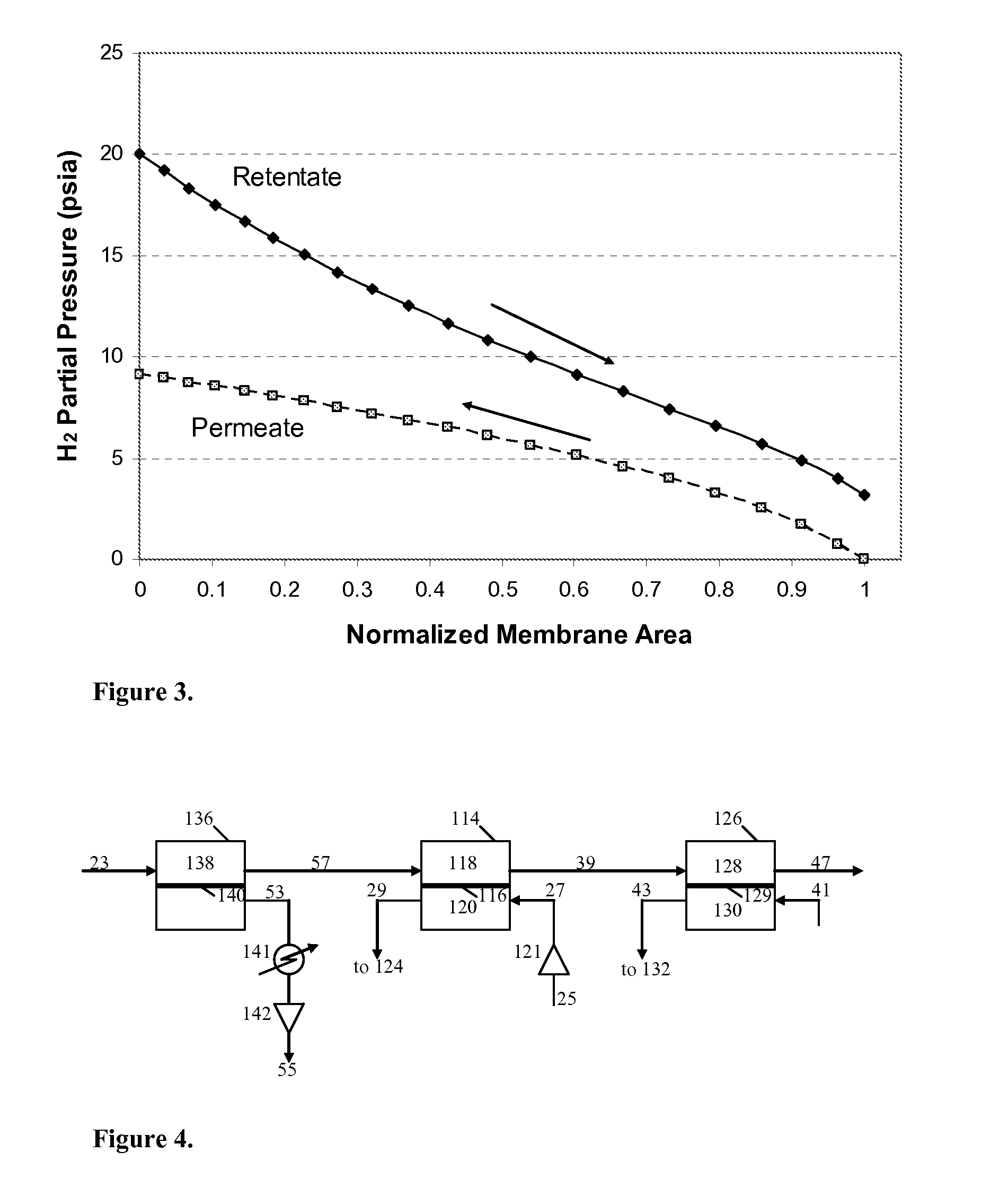
[0034]An exemplary arrangement of HTMs for co-production of H2 (e.g., high-purity H2) and electrical power in an IGCC plant with CO2 capture in accordance with an alternative embodiment of the present invention is illustrated in FIG. 4. As used in the present invention, “high-purity H2” gas, it is meant H2 gas that is at least 95% by volume H2. More preferably, such gas will be at least 99% by volume H2 and most preferably, such gas will be greater than 99.9% by volume H2. The process flow diagram (PFD) only shows the portions for the HTMs of the IGCC plant. The processing and equipment upstream and downstream of the HTMs can be the same as described above and shown in FIG. 1. The stream summary for this particular computer-simulated example is given in Table 2.

TABLE 2Stream summary for PFD shown in FIG. 4.Stream23573947532943Flow (lbmol / hr)386803029023030205208389157105438Flow (kpph)713.6696.7682.1677.016.925...


PUM


Abstract

The present invention relates to the use of low pressure N2 from an air separation unit (ASU) for use as a sweep gas in a hydrogen transport membrane (HTM) to increase syngas H2 recovery and make a near-atmospheric pressure (less than or equal to about 25 psia) fuel for supplemental firing in the heat recovery steam generator (HRSG) duct burner.

Description

CROSS REFERENCE TO RELATED APPLICATIONS[0001]The present invention claims priority both to U.S. patent application Ser. No. 60 / 879,615, filed Jan. 10, 2007 and to U.S. patent application Ser. No. 60 / 925,800, filed Apr. 23, 2007, the entire contents of both applications incorporated herein by reference.GOVERNMENT SUPPORT[0002]The present invention was made in part with support from United States Department of Energy, contract no. DE-FC26-05NT42469. Accordingly, the United States Government may have certain rights to this invention.FIELD OF THE INVENTION[0003]The present invention relates to the use of low pressure N2 from an air separation unit (ASU) as a sweep gas in a hydrogen transport membrane (HTM) to increase syngas H2 recovery and make a near-atmospheric pressure (less than or equal to about 25 psia) fuel for firing in the heat recovery steam generator (HRSG) duct burner.BACKGROUND OF THE INVENTION[0004]Conventional IGCC carbon capture methods: The typical process for CO2 capt...

Claims


Application Information

Patent Timeline
Patent Type & Authority Applications(United States)
IPC IPC(8): F02C3/20
CPCC01B3/501C01B2203/0405C01B2203/0475C01B2203/0495Y02E20/18B01D53/226F01K23/068B01D2257/108Y02E20/185C01B2203/86Y02P20/129Y02P30/00
Inventor PANUCCIO, GREGORY J.RAYBOLD, TROY M.JAMAL, AGILDRNEVICH, RAYMOND FRANCIS
Owner PRAXAIR TECH INC
Why Eureka
Try Eureka