
Ink for printing on low energy substrates

a low-energy substrate and ink technology, applied in the field of ink compositions of water-based inks, can solve the problems of high surface tension, difficult printing, and difficulty in printing, and achieve the effect of reducing the tendency of printing drops, different viscosity, and high printing efficiency

Inactive Publication Date: 2010-03-18
EASTMAN KODAK CO
View PDF7 Cites 5 Cited by
  • Summary
  • Abstract
  • Description
  • Claims
  • Application Information

AI Technical Summary

Benefits of technology

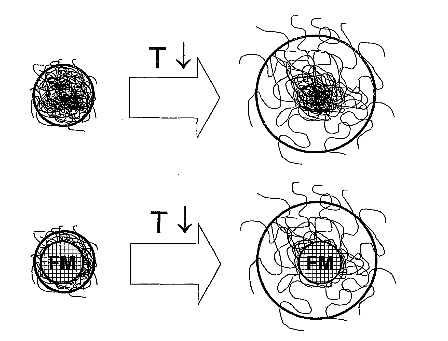
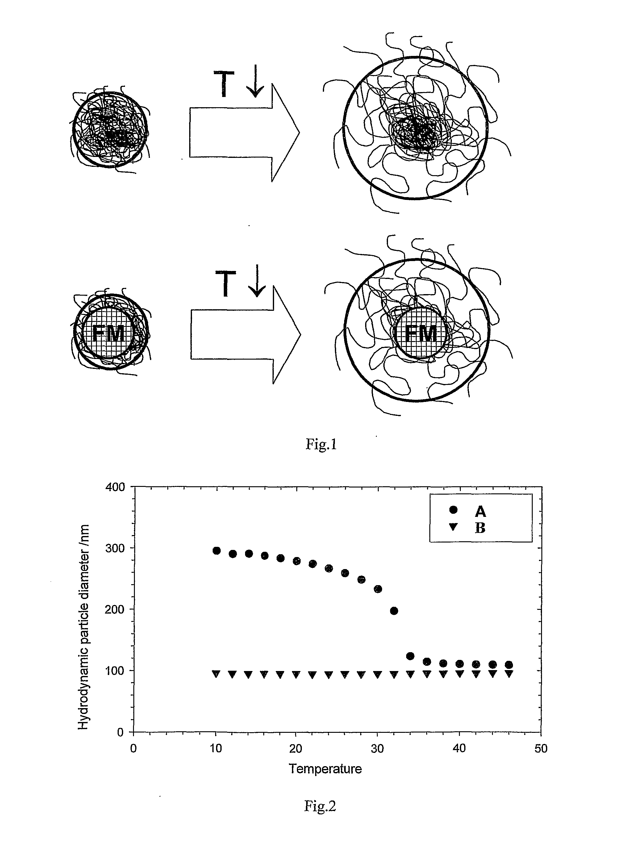
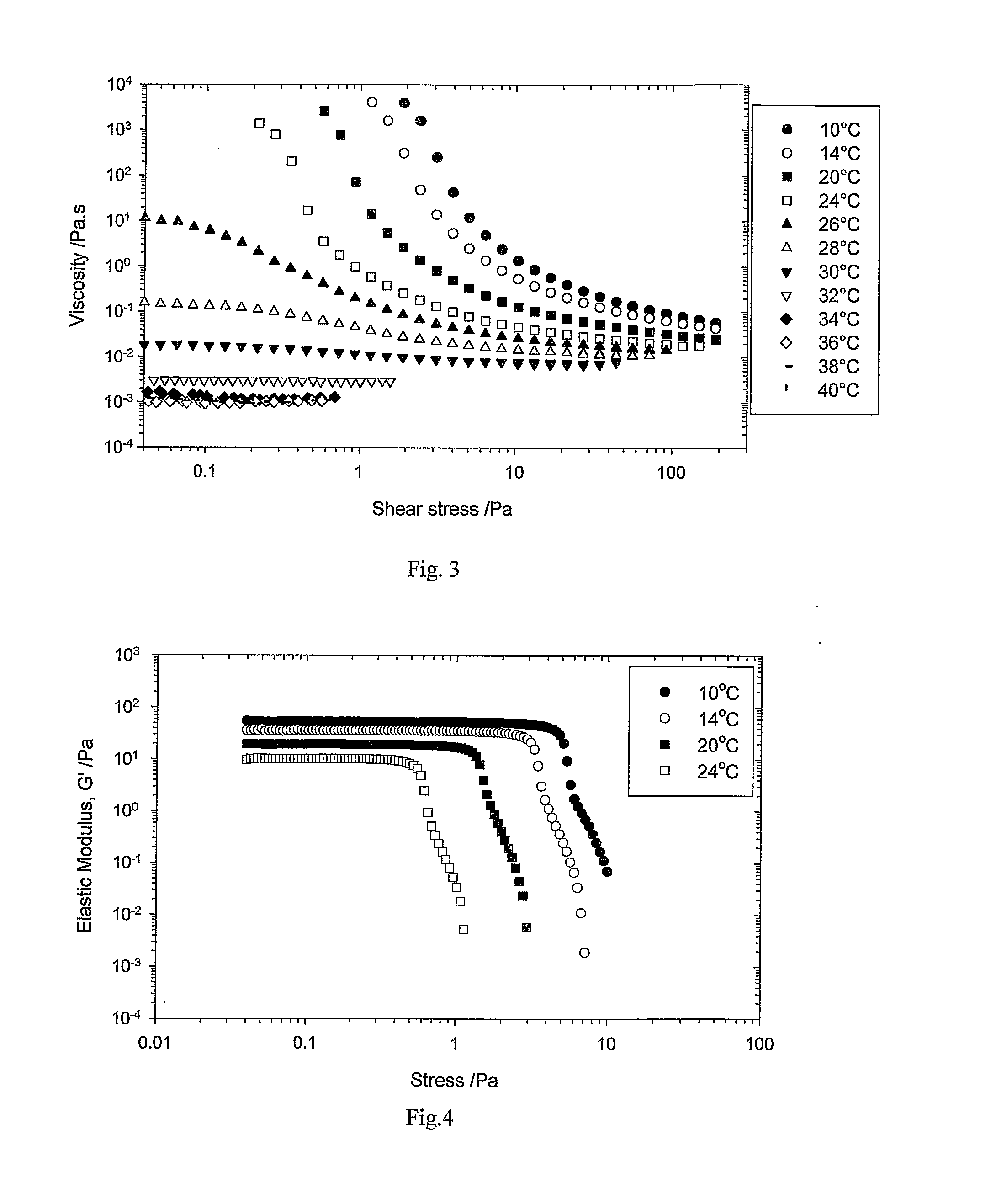
[0029]The ink composition comprising stimulus-responsive polymer particles is primarily water-based, thereby addressing environmental concerns, is redispersible and can adhere to a wide range of surfaces and in particular to impermeable surfaces normally used for packaging, such as polyethylene and polypropylene. The composition has a viscosity in the printhead such that it is conveniently jettable though a continuous inkjet printhead and will not harden irreversibly around the orifices or on the catcher where the ink is recirculated in the printer. Moreover the stimulus-responsive polymers can be selected such that the ink can have a significantly different viscosity on the substrate at the ambient temperature, thereby reducing the tendency of the printed drops to flow so that successive drops do not damage image quality

Problems solved by technology

All of these practices have significant disadvantages.
However, the nature of the surface, particularly its surface energy, can still present difficulties.
Unfortunately water has a very high surface tension, which makes it particularly difficult to apply satisfactorily as droplets onto low energy, impermeable surfaces.
Unfortunately, many aqueous inks are either not capable of sufficiently wetting the substrate or do not dry quickly enough at the speeds used in inkjet printing, especially in continuous inkjet printing wherein the time between successive drops is very significantly shorter than for drop-on demand inkjet systems.
Radiation-curable water-based inks have also been described for use in an inkjet process (patent application WO 99 / 07796), but often the resulting printed layers can be thick and may lack desirable physical properties, for example, sufficient flexibility.
Such inks are usually high in viscosity, which makes the jetting process difficult, and it is often necessary to minimise viscosity by heating the ink significantly prior to printing.
In addition, the curing process, which can involve complex equipment and considerable energy consumption, can in some cases be quenched by oxygen and require special measures, such as ‘blanketing’ under nitrogen.
Moreover the printed image may be insufficiently hardened, or curing may continue after the initial curing time under the radiation source.
This method avoids the use of volatile solvents but is, however, non-aqueous and one problem is the build-up of wax on the image where multiple droplets are placed to form a composite colour.
However, the air-drying polymer can also harden around the orifices of a printhead, or on the recirculation catcher of a continuous inkjet printer, causing the same problems of poor image quality and productivity as mentioned hereinbefore for solvent-based inks.
These polymers are extremely difficult to remove once they have cross-linked on the recirculation catcher, since eventually the hardened deposits block the catcher preventing further recirculation of non-printed drops, making them unsuitable for continuous inkjet printing.
Typically on jetting an ink drop onto paper the drop will lose water by penetration therein and by evaporation, increasing the concentration thereby resulting in a rapid increase in viscosity.
However neither of the compositions disclosed in U.S. Pat. No. 5,462,591 and JP06248208 would be suitable for use under the high shear conditions employed during continuous inkjet printing, since polymer stringing could occur and drop ‘break-off’ would become unreliable.
However, the inks are dependent on significant heating (above 70° C.) of the substrate to achieve the required viscosity for droplet immobilisation, which restricts the type of substrates which can be printed by this method.
However, although stimulus-responsive materials, such as N-isopropylacrylamide, could be used to encapsulate pigment, the patents do not teach the use of these materials to enable a lower viscosity of ink in the printhead versus that of the substrate so that it could be used to print on a wide variety of substrates.

Method used


Image

  • Ink for printing on low energy substrates
  • Ink for printing on low energy substrates
  • Ink for printing on low energy substrates

Examples


example 1

Preparation of Thermally-Sensitive Polymer Particles

[0116]15.8 g N-isopropylacrylamide (obtainable from Aldrich), 0.301 g N,N′-methylenebisacrylamide (obtainable from Aldrich) and 0.31 g sodium dodecyl sulfate (SDS) were added to a 11 double-walled glass reactor equipped with a mechanical stirrer and condenser. 900 ml water was added and the mixture warmed to 40° C., purged with nitrogen for 30 min. while being stirred at 500 rpm. The solution was then heated to 70° C. and 0.60 g potassium persulfate initiator (dissolved in 100 ml deionised water which had been purged with nitrogen) was added quickly to the reactor. The mixture was stirred at 400 rpm at 70° C. for 5 h under nitrogen. The reaction mixture rapidly became opalescent then became white. The heating was switched off and the mixture left to cool down to room temperature. The reaction yielded a white latex which was filtered, then dialysed until the conductivity of the permeate was less than 10 μS. The dialysed latex was fr...

example 2

Preparation of Co-Polymer Particles which are Thermally-Sensitive

[0119]13.7 g N-isopropylacrylamide (obtainable from Aldrich), 0.272 g N,N′-methylenebisacrylamide (obtainable from Aldrich), 0.365 g acrylic acid (obtainable from Aldrich) and 0.272 g sodium dodecyl sulfate were added to a 11 double-walled glass reactor equipped with a mechanical stirrer and condenser. 900 ml water was added and the mixture warmed to 40° C., purged with nitrogen for 1 h 30 min. while being stirred at 400 rpm. The solution was then heated to 70° C. and 0.540 g potassium persulfate initiator (dissolved in 90 ml deionised water which had been purged with nitrogen) was added quickly to the reactor. The mixture was stirred at 200 rpm at 70° C. for 6 h under nitrogen. The reaction mixture rapidly became opalescent then became white. The heating was switched off and cooled down. The reaction yielded a white latex which was filtered, then dialysed for several days until the conductivity of the permeate was 7 μ...

example 3

Preparation of a Pigment Dispersion

[0120]30 g Monarch 880 carbon black (Cabot) was mixed with 214.4 g demineralised water, followed by 55.6 g Joncryl™ HPD96DMEA dispersant (available from Johnson Polymer). Zirconia beads of 0.6-0.8 mm diameter were added to the mixture, which was milled until the carbon black could not be milled down further. The zirconia beads were removed by filtration leaving a black dispersion with a mean particle size of 98 nm.


PUM

PropertyMeasurementUnit
diameteraaaaaaaaaa
equivalent spherical diameteraaaaaaaaaa

Abstract

The invention provides an aqueous inkjet ink composition comprises a polymeric compound comprising discrete particles responsive to an external stimulus, and a functional material, wherein the functional material may be incorporated as part of the polymeric particles, the particles causing the composition to have a first rheological state and a different second rheological state in response to a stimulated change in conditions, the first rheological state being associated with a first lower viscosity of the composition, wherein the particles have a first lower volume, enabling the composition to pass through an inkjet printhead orifice and the second rheological state being associated with a second higher viscosity of the composition, wherein the particles have a second higher volume, enabling immobilisation of droplets of the composition on a substrate. The inkjet composition is particularly useful in a continuous inkjet printing system for printing onto a wide range of surfaces including impermeable surfaces.

Description

FIELD OF THE INVENTION[0001]The present invention relates to an aqueous ink composition suitable for printing on various substrates, especially impermeable substrates, and particularly for continuous inkjet printing systems.BACKGROUND OF THE INVENTION[0002]Inkjet printing is a non-impact method for producing images by the deposition of ink droplets in a pixel-by-pixel manner to an image-recording element in response to digital signals. It is used widely for commercial and business applications for printing on various substrates from paper to cable marking or wide format vinyl sheeting and across markets ranging from industrial labelling to short-run printing to desktop document and pictorial imaging.[0003]There are various methods which may be utilized to control the deposition of ink droplets on the image-recording element to yield the desired image. In one process, known as continuous inkjet, ink is supplied under pressure through orifices that produce jets of ink, which break up ...

Claims


Application Information

Patent Timeline
Patent Type & Authority Applications(United States)
IPC IPC(8): C09D11/10B41J2/02H01F1/26H01B1/12
CPCC09D11/30C09D11/101
Inventor GIBSON, DANUTAHIGGINS, JOHN M.DESROUSSEAUX, STEPHANIE V.HOWE, ANDREW M.HOWE, ANDREWCLARKE, ANDREWNICHOLAS, CHRISTIAN V.HONE, JOHN H.
Owner EASTMAN KODAK CO
Learn More