
Radially inwardly directed electron beam source and window assembly for electron beam source or other source of electromagnetic radiation

Inactive Publication Date: 2010-03-18
DALLY EDGAR B +1
View PDF3 Cites 8 Cited by
  • Summary
  • Abstract
  • Description
  • Claims
  • Application Information

AI Technical Summary

Benefits of technology

[0010]In accordance with an aspect of the present invention, a system and method are provided for transmitting an electron beam, x-rays, or other form of high energy electromagnetic radiation from an evacuated space in which the radiation is generated to an external region, for example, to treat flowing media. In accordance with one embodiment, the system comprises an electron beam generator that preferably employs a thermionic cathode. Advantageously, cold electron emission cathodes do not require heating power. In accordance with one preferred embodiment, the electron beam generator comprises a cold electron emitting surface in sheet form, which can be shaped to different patterns of emission, and emits electrons from a large surface area. The cathode is disposed on the inside of a cylinder. Constructed with or without a control grid, and with an applied negative high voltage between the cathode and a grounded cylinder of smaller diameter, for example, a tube or window assembly, a beam of electrons is accelerated in a direction perpendicular to the common axis of the cylinders. The smaller cylinder is preferably provided with windows constructed of sufficiently thin material, so that the electrons pass through such windows into an inner cylindrical region within the smaller cylinder. The electrons irradiate flowing media passing through the inner cylindrical region. In accordance with a preferred embodiment, the flowing media passing through the inner cylindrical region is effectively and efficiently processed for the purpose of destroying toxic, hazardous, or noxious organic and / or inorganic compounds contained in air or other gaseous media flowing through the cylindrical region, so as to destroy or inactivate bacteria, viruses, fungi, or mold spores in such flowing media; or to sterilize the contents of the flowing media; or to treat fluidized grains, herbs, or other similar products to provide sterilization; or to destroy chemical warfare agents.
[0013]The thermal expansion coefficients of the inner and outer cylinders are approximately equal to minimize the mechanical stress and distortion of the cylinders during the bonding process construction of the window component subassembly.
[0014]An additional cylinder having an outside diameter smaller than the inside diameter of the inner foil window cylinder and bonded to it may be added to the window component subassembly to further reduce mechanical and thermal stress in the window foil and / or to reduce or prevent corrosion of the inner surface of the window foil by material being treated in the application space. In accordance with one embodiment, both the inner window foil cylinder and the additional cylinder are constructed from titanium.

Problems solved by technology

For example, various devices are known for destroying toxic, hazardous, or noxious organic and / or inorganic compounds contained in flowing air or other media.
The configurations of known electron beam and other electromagnetic radiation devices may typically incorporate a structure to control the emitted radiation, but are not generally conducive to the effective and efficient transmission of the emitted radiation or the dissipation of heat that is generated.
Moreover, known configurations are not scalable.
For example, the configurations of known electron beam devices are not generally conducive to the effective and efficient treatment of the flowing media.
Moreover, known configurations are not scalable to treat large volumes of flowing media.

Method used


Image

  • Radially inwardly directed electron beam source and window assembly for electron beam source or other source of electromagnetic radiation
  • Radially inwardly directed electron beam source and window assembly for electron beam source or other source of electromagnetic radiation
  • Radially inwardly directed electron beam source and window assembly for electron beam source or other source of electromagnetic radiation

Examples


Embodiment Construction

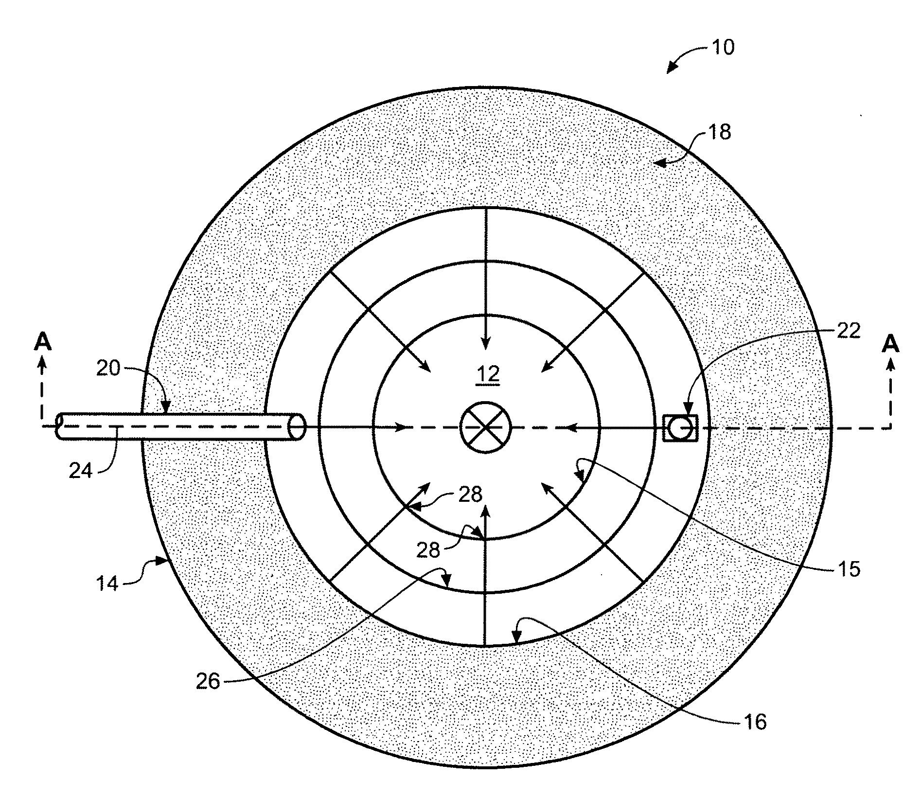
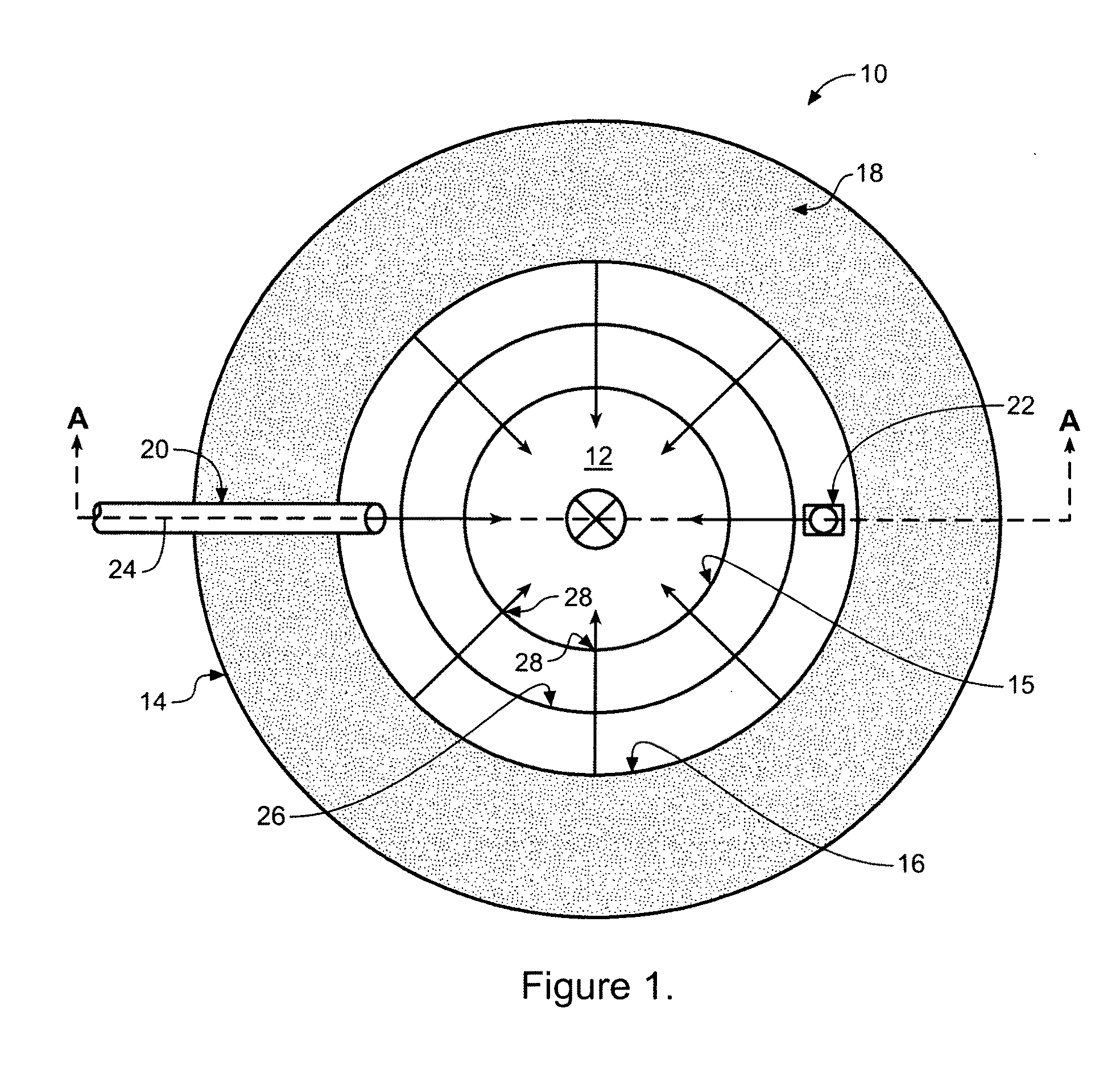
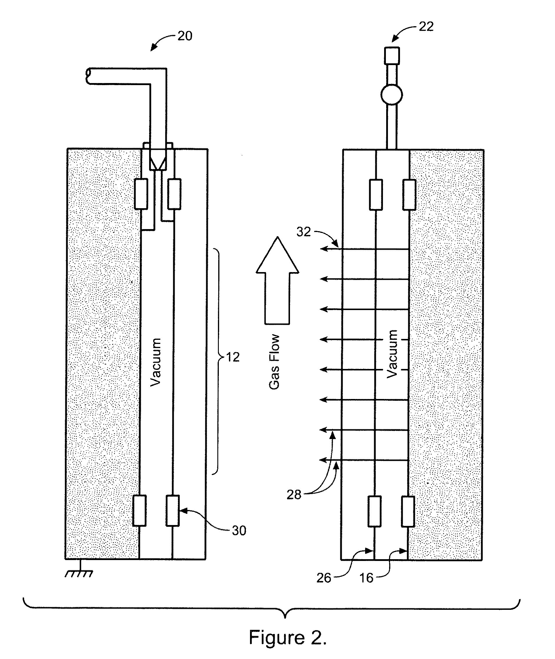
[0042]Generally, in accordance with an aspect of the present invention, an electron beam system in accordance with various embodiments preferably employs cold electron emission technology to produce sheets of emitters deployed in a cylindrical geometry. The cathode is held in a vacuum by a grounded, sealed cylindrical housing and insulated from ground potential. The cylindrical housing is vacuum sealed, and can be equipped with an ion pump. A high voltage power supply accelerates emitted electrons in a radially inward direction towards the centerline of the cylindrical geometry. The electrons pass in vacuum through windows constructed of thin foil material (e.g., titanium or a titanium compound) preferably comprising a window assembly and emerge into a cylindrical region, for example, an application space where irradiation of matter or compounds contained in an air stream or other media flowing through the cylindrical region occurs. The cold electron emitting surfaces can be masked ...


PUM


Abstract

A system and method to provide uniform, high intensity radially inwardly directed electron beams to the interior of a cylindrical volume for the purpose of destroying toxic, hazardous, or noxious organic and / or inorganic compounds contained in air or other media flowing through a cylindrical region; or to destroy or inactivate bacteria, viruses, fungi, or mold spores in such flowing media; to sterilize contents of flowing media; to treat fluidized grains, herbs, or other products; or to destroy chemical warfare agents. A window assembly to transmit electromagnetic radiation, for example, an electron beam, x-rays, or other high energy electromagnetic radiation, is also disclosed.

Description

CROSS-REFERENCE TO RELATED PATENT APPLICATION[0001]This application relates to U.S. Provisional Patent Application No. 61 / 135,138 filed on Jul. 17, 2008, entitled RADIALLY INWARDLY DIRECTED ELECTRON BEAM SOURCE FOR TREATMENT OF FLOWING MEDIA, which is hereby incorporated herein in its entirety by this reference.BACKGROUND OF THE INVENTION[0002]1. Field of the Invention[0003]The present invention relates generally to apparatus and processes for producing electromagnetic energy, and, more particularly, to systems and methods to transmit high energy electromagnetic radiation from a source to an external region, for example, to treat materials and, more particularly, to treat a flow of matter containing a harmful or noxious component. Specifically, one embodiment of the present invention provides a system and method to provide a uniform, high-intensity electron beam to the interior of a cylindrical volume for the purpose of destroying toxic, hazardous, or noxious organic and / or inorgani...

Claims


Application Information

Patent Timeline
IPC IPC(8): G21K1/08B01J19/12
CPCB01J19/085H01J5/18G21K5/10
Inventor DALLY, EDGAR B.ESPINOSA, ROBERT J.
Owner DALLY EDGAR B
Learn More