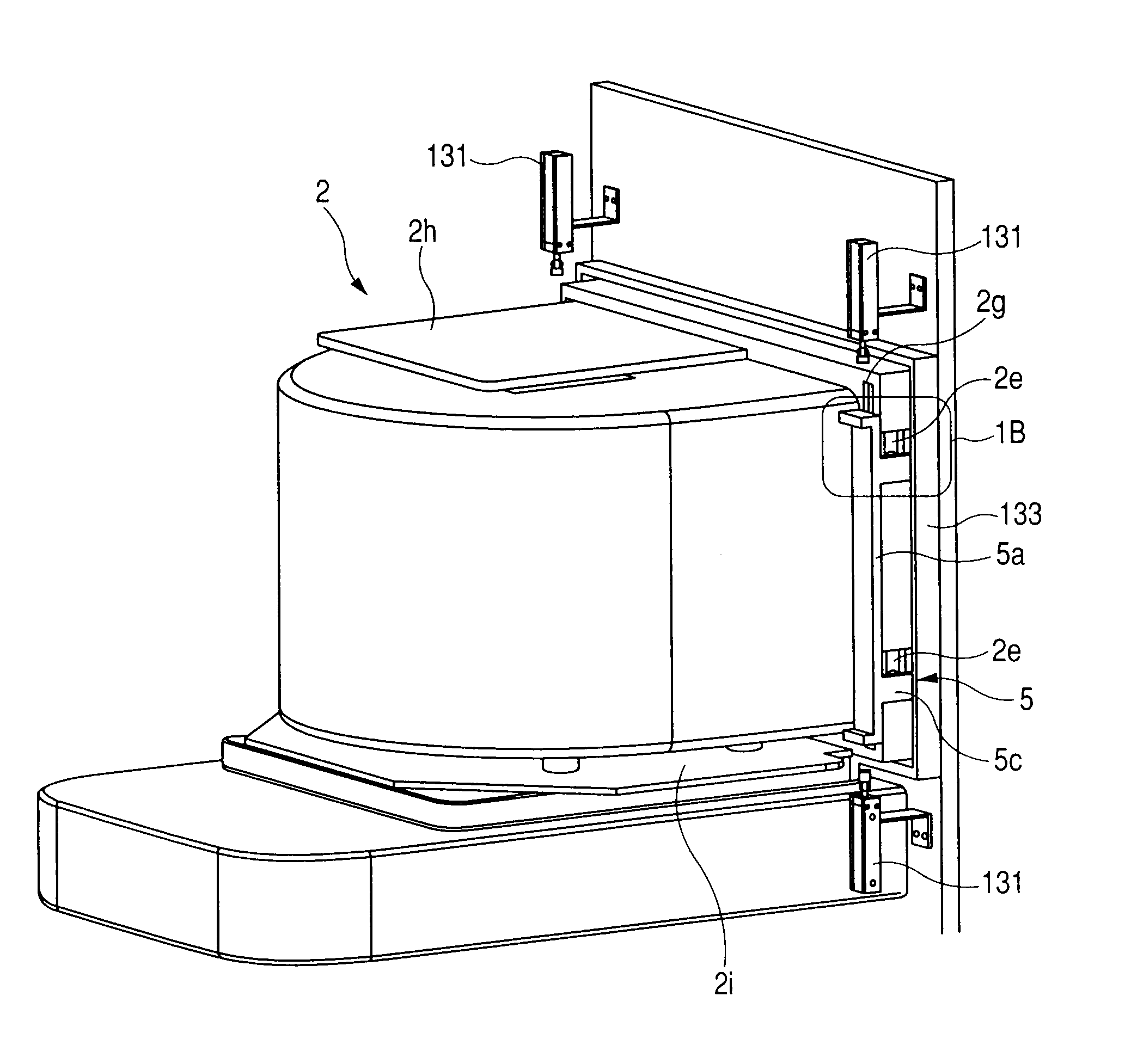
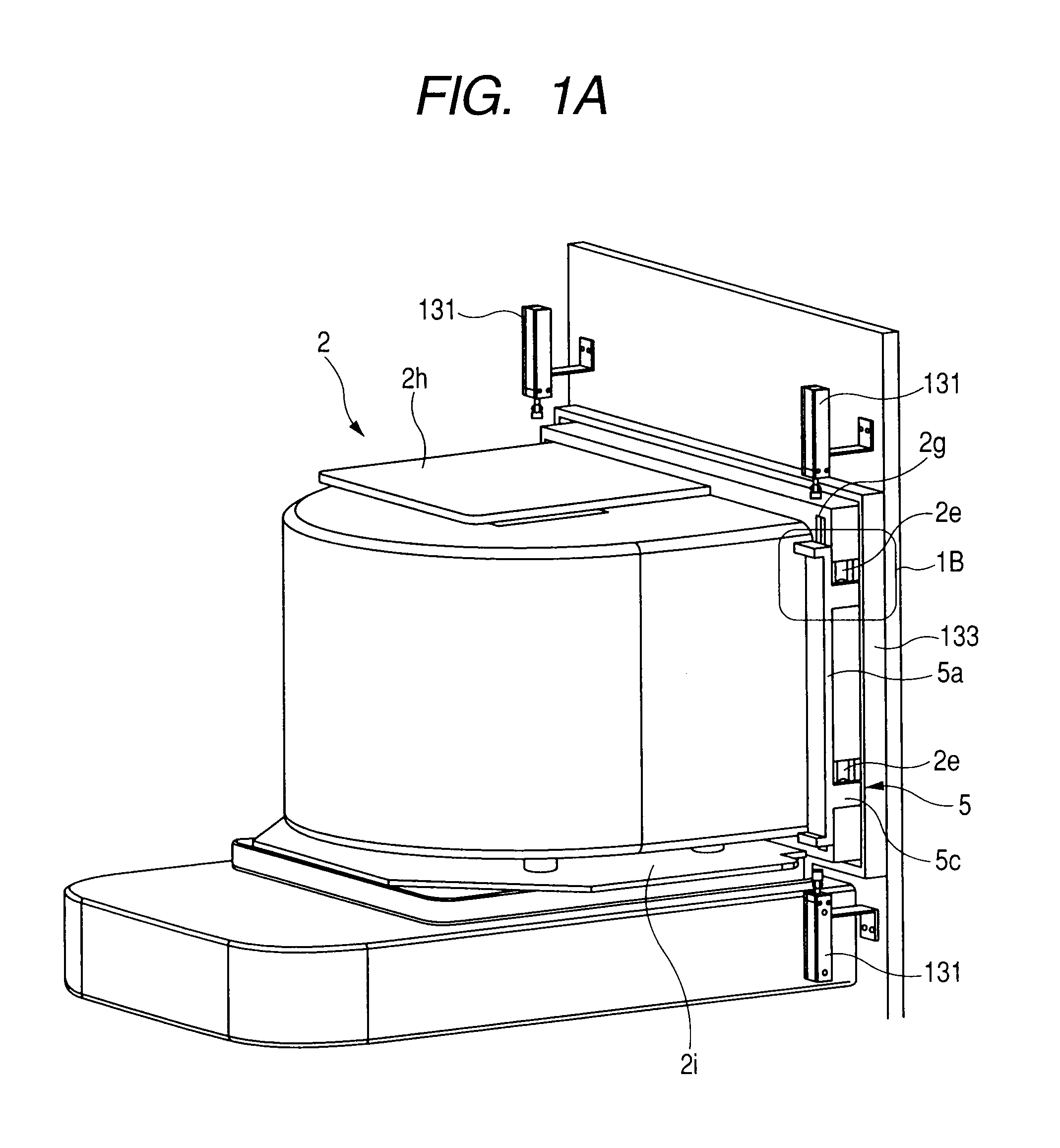
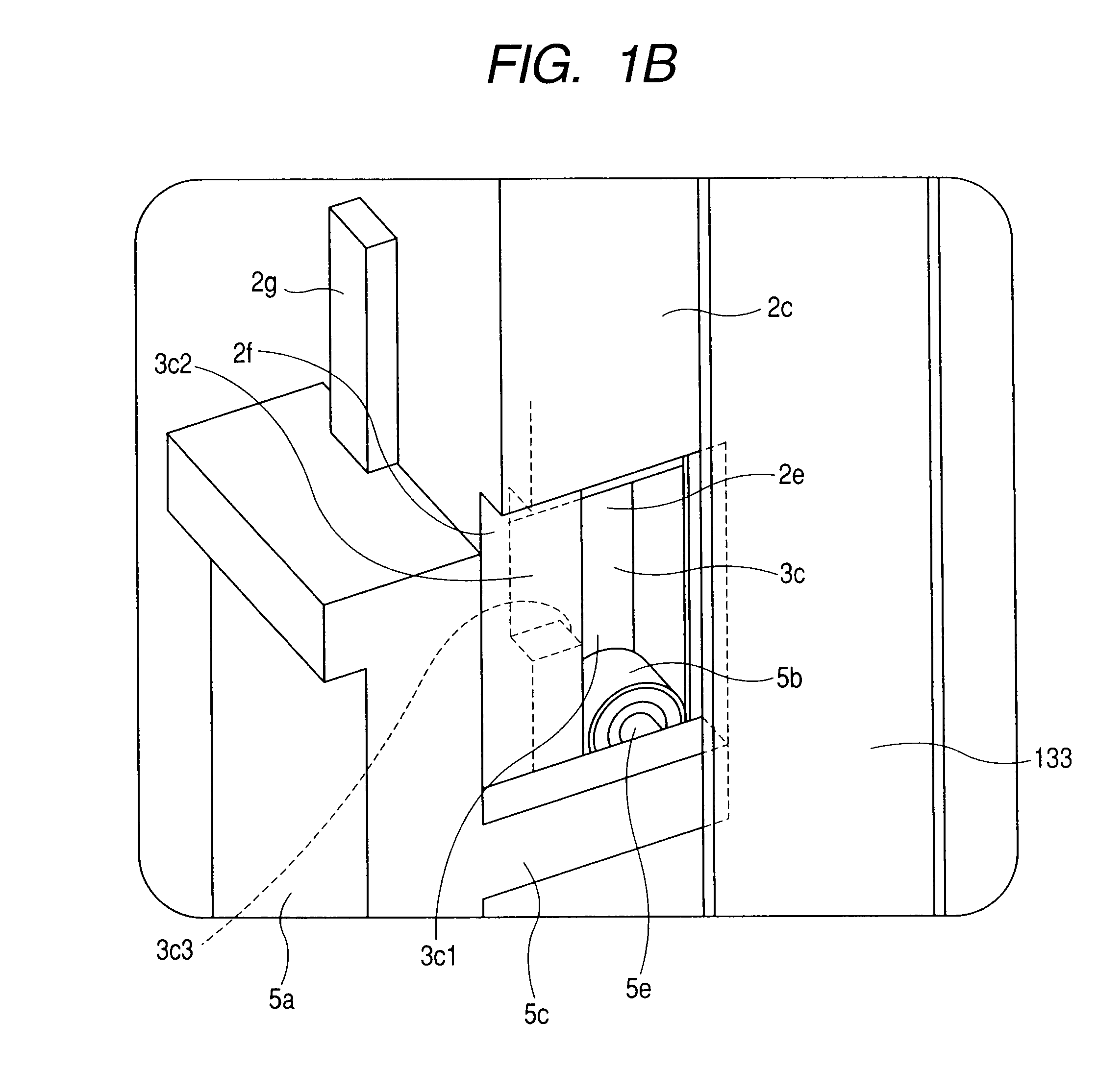
[0014]According to the present invention, in the state in which the lid is fixed on the pod, the surface of the lid is flat. In addition, the lid does not have a movable member that is to be accessed and operated from the outside. Therefore, generation of dust with operation of a so-called latch tongue on the front surface of the door, which conventional systems have, can be completely eliminated. In addition, the lid is a simple flat plate-like member that does not have structures provided in the interior thereof, unlike with conventional lids.
[0015]Therefore, dust or the like can easily be removed by cleaning. In addition,
dust particles or the like do not adhere on the lid in a manner that removal thereof is difficult, and the degree of cleanness of the lid alone can be maintained high. Specifically, since the engaged recess provided on the lid has a simple groove shape,
machining and cleaning of the lid is much easier than conventional lids. Change of the
diameter of wafers used in semiconductor manufacturing process from 300 mm (the
diameter of currently used wafers) to 450 mm have been considered. In pods that store such large-
diameter wafers, it is required, with an increase in the size of the lid, to prevent deformation such as warpage and bending of the lid and to fix the lid reliably with adequate strength in fixation. The lid of the pod according to the present invention has a simple flat plate-like structure, and therefore the lid can easily be made light in weight, and the structure that adds rigidity of the lid while achieving a decrease in the weight can be used. Thus, such requirements can easily be met with reliability.
[0016]According to the present invention, it is also possible that the lid be adapted to be always biased in the direction for sealing the pod opening in the state in which the lid is fixed on the pod body. This enables improvement in the
air tightness of the pod and reduction of possibility of dust generation due to vibration of the lid during transferring etc. Furthermore, since the surface of the lid can be made flat, a seal member may be provided on the lid or the surface of the door opposed thereto to isolate the space defined between the lid and the door from the surrounding space. Thus,
diffusion of dust or air coming from the
outer space that the lid has brought into the mini-environment is prevented with reliability. In addition, by reducing the pressure in the
closed space formed between the lid and the door by the seal member, additional holding of the lid by the door can be provided besides holding of the lid by suction. Furthermore, means for opening and closing the lid is disposed and operates basically in the region outside the pod and the mini-environment. Therefore, if dust is generated from this means, frequency of
diffusion of such dust into the pod or the mini-environment is greatly reduced as compared to conventional systems.
[0017]In the present invention, what is called a latch mechanism for fixing the lid to the pod may be adapted to be driven in the vertical direction and fixation of the lid is designed to be achieved at a lower position. In this case, fixation of the lid to the pod is achieved by the latch mechanism's own weight. Thus, even when an operation error occurs in the means for driving the latch mechanism upon opening or closing the lid, the latch mechanism can be kept in the position for fixing the lid. Thus, the lid can be kept closed, and the
interior space of the pod can continue to be kept clean. In the structure disclosed in Japanese
Patent Application Laid-Open No. 2001-077177, for example, in a situation in which the key member and the operated portion of the latch mechanism can hardly be separated due to, for example, erroneous engagement, it may be necessary, for example, to disassemble the lid in order to separate them. In the case of the container according to the present invention, access to the latch mechanism can be made from the external space outside the mini-environment (e.g. from the lateral side of the pod) to forcibly cause the latch mechanism to operate. Therefore, if the latch mechanism becomes inoperable by malfunction, it is possible to repair the trouble relating to the latch mechanism easily by performing the forcible operation. Furthermore, whether the latched state has been appropriately established or not can easily be checked from outside with eyes without providing additional means or operation.
[0018]In the present invention, in the drive mechanism for operating the latch mechanism, the size of an operation portion (i.e. drive contact surface that will be described later) for operating the latch mechanism may be arbitrarily designed. Therefore, the degree of accuracy in the position at which the pod is kept when the lid is opened by the door may be lower than in the case of conventional systems. In the case of conventional systems, detachment of the lid from the pod and establishment of communication between the
interior space of the pod and the mini-environment cannot be performed unless a high degree of accuracy is achieved in all of the
fixed position of the lid relative to the placement position, the
fixed position of the pod relative to the opening portion and the position of contact of the door to the lid determined by the latch mechanism. According to the present invention, at least requirement for accuracy of the
fixed position of the lid and pod determined by the latch mechanism is relaxed, which advantageously leads, for example, to a simplification of the operation program of the lid opening and closing apparatus and stability of operation.


