Water cooling device for model toy engine

Inactive Publication Date: 2010-03-11
LO MAO SHENG
View PDF1 Cites 2 Cited by
  • Summary
  • Abstract
  • Description
  • Claims
  • Application Information

AI Technical Summary

Benefits of technology

[0003]As mentioned above, the conventional model toy engine does not use a water cooling device. When a model toy engine operates at a high speed for a long time, the temperature of the engine will rise persistently, which decreases the horsepower of the model toy engine and reduces the competitiveness of the model toy in races. Besides, the service life of the model toy engine is also affected thereby.
[0004]The primary objective of the present invention is to provide a water cooling device for a model toy engine to overcome the conventional problems, wherein a radiator is installed above a model toy engine, and the heat generated by the engine boils the water inside the radiator into vapor; the vapor flows into the pipe, and the cooler cools the vapor into water, and then the condensed water flows back to the radiator, whereby the temperature of the engine is maintained within a specified range, wherefore the present invention can prevent the engine from overheat or burnout and prolongs the lifetime of the engine.
[0005]To achieve the abovementioned objective, the present invention proposes a water cooling device for a model toy engine, which comprises an engine, a radiator, a pipe, a cooler, and a water tank. The radiator is fixedly installed on the engine. The radiator contains water and has a water outlet and a water inlet on the top thereof. A pipe interconnects the water outlet and the water inlet. A cooler and a water tank are installed to connect with the pipe. The heat generated by the engine boils the water inside the radiator into vapor. The vapor flows into the pipe, and the cooler cools the vapor into water, and then the condensed water flows back to the radiator. The cooling cycle is repeated persistently to dissipate the heat generated by the engine. Therefore, the present invention can prevent the engine from overheat or burnout, avoid horsepower falling, and prolong the lifetime of the engine.
[0007]1. In the present invention, the heat generated by the engine boils the water inside the radiator into vapor. The vapor flows into the pipe, and the cooler cools the vapor into water, and then the condensed water flows back to the radiator. Thereby, the temperature of the engine is maintained within a specified range. The present invention can undertake the cooling cycles without using any motor or pump. Therefore, the present invention will not consume additional energy.
[0008]2. In the present invention, the water flowing back to the radiator has been cooled down, and the cooling cycle is repeated persistently to maintain the temperature of the engine within a specified range. Thus, the temperature of the engine operating at a high speed will not rise continuously, and the horsepower will not be lowered by high temperature. Therefore, the present invention can maintain the horsepower of a model toy engine and favors operating the model toy at a high speed.
[0009]3. In the present invention, the radiator automatically sends the vapor into the pipe, and the cooler cools the vapor into water, and then the condensed water flows back to the radiator. The cooling cycle is repeated persistently to maintain the temperature of the engine within a specified range. Therefore, the present invention can prevent the engine from overheat or burnout and prolongs the lifetime of the engine.

Problems solved by technology

When a model toy engine operates at a high speed for a long time, the temperature of the engine will rise persistently, which decreases the horsepower of the model toy engine and reduces the competitiveness of the model toy in races.
Besides, the service life of the model toy engine is also affected thereby.

Method used


Image

  • Water cooling device for model toy engine
  • Water cooling device for model toy engine
  • Water cooling device for model toy engine

Examples


Embodiment Construction

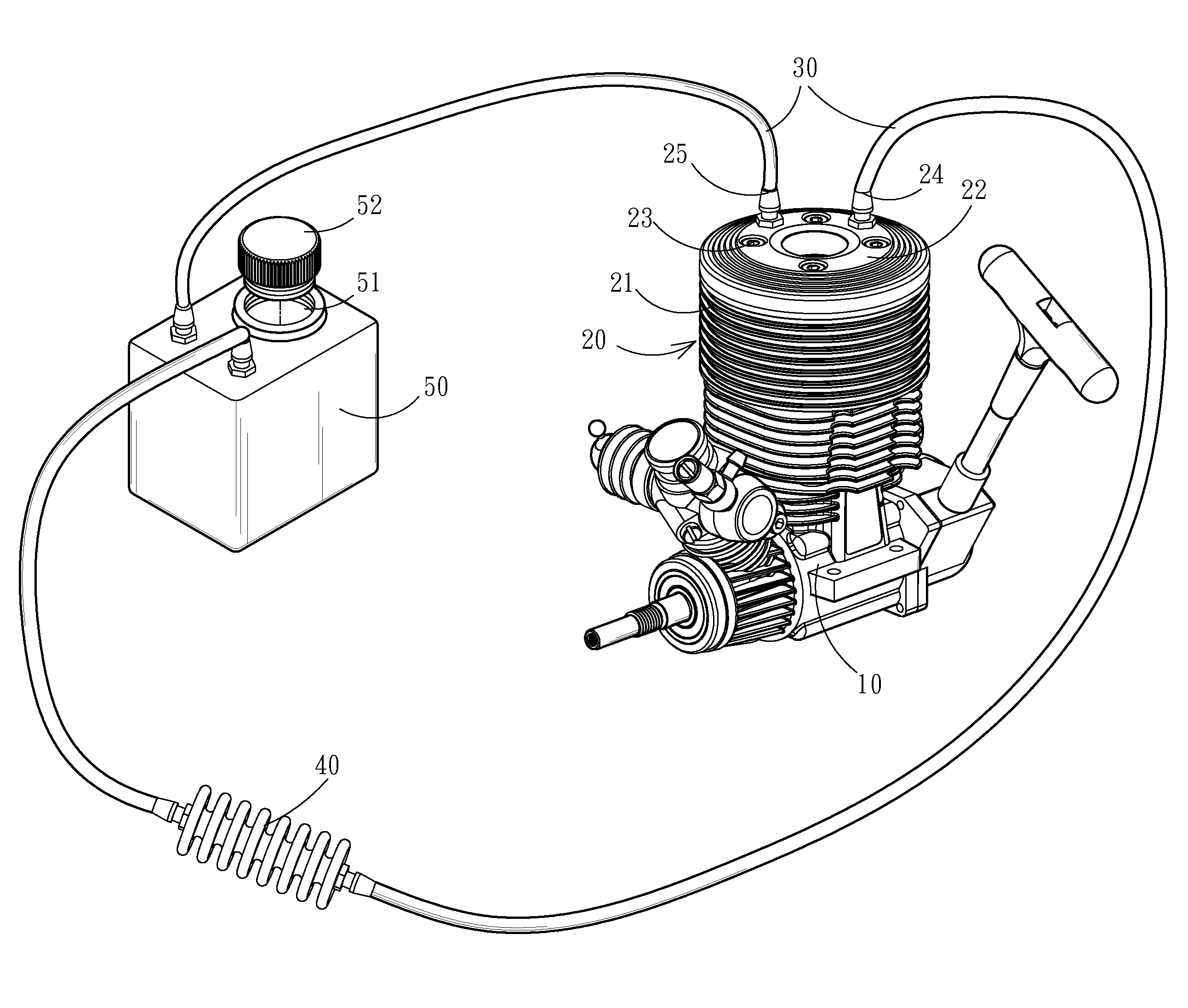
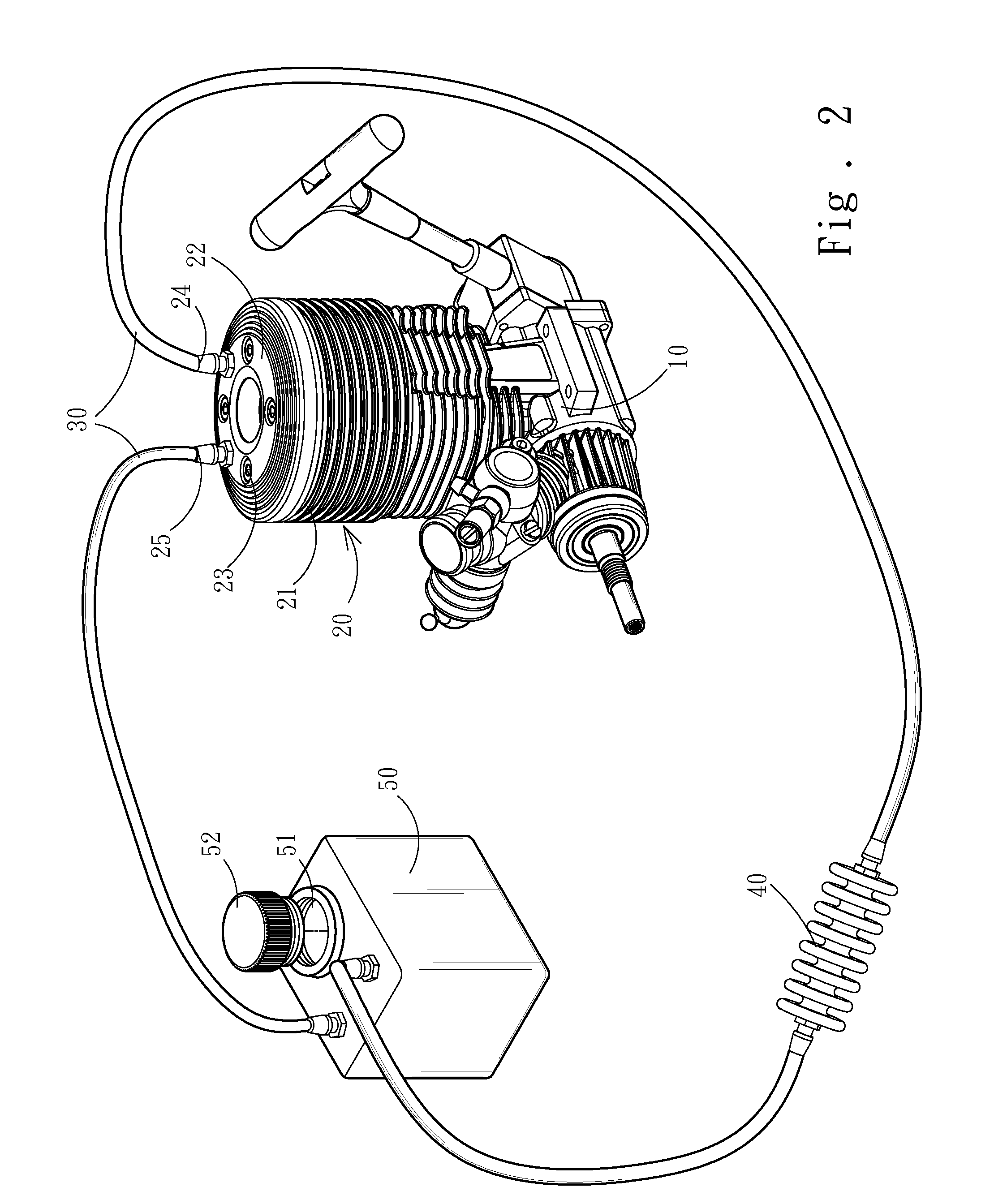
[0014]Refer to FIG. 2, FIG. 3A, and FIG. 3B. The water cooling device for a model toy engine of the present invention comprises an engine 10, a radiator 20, a pipe 30, a cooler 40, and a water tank 50.

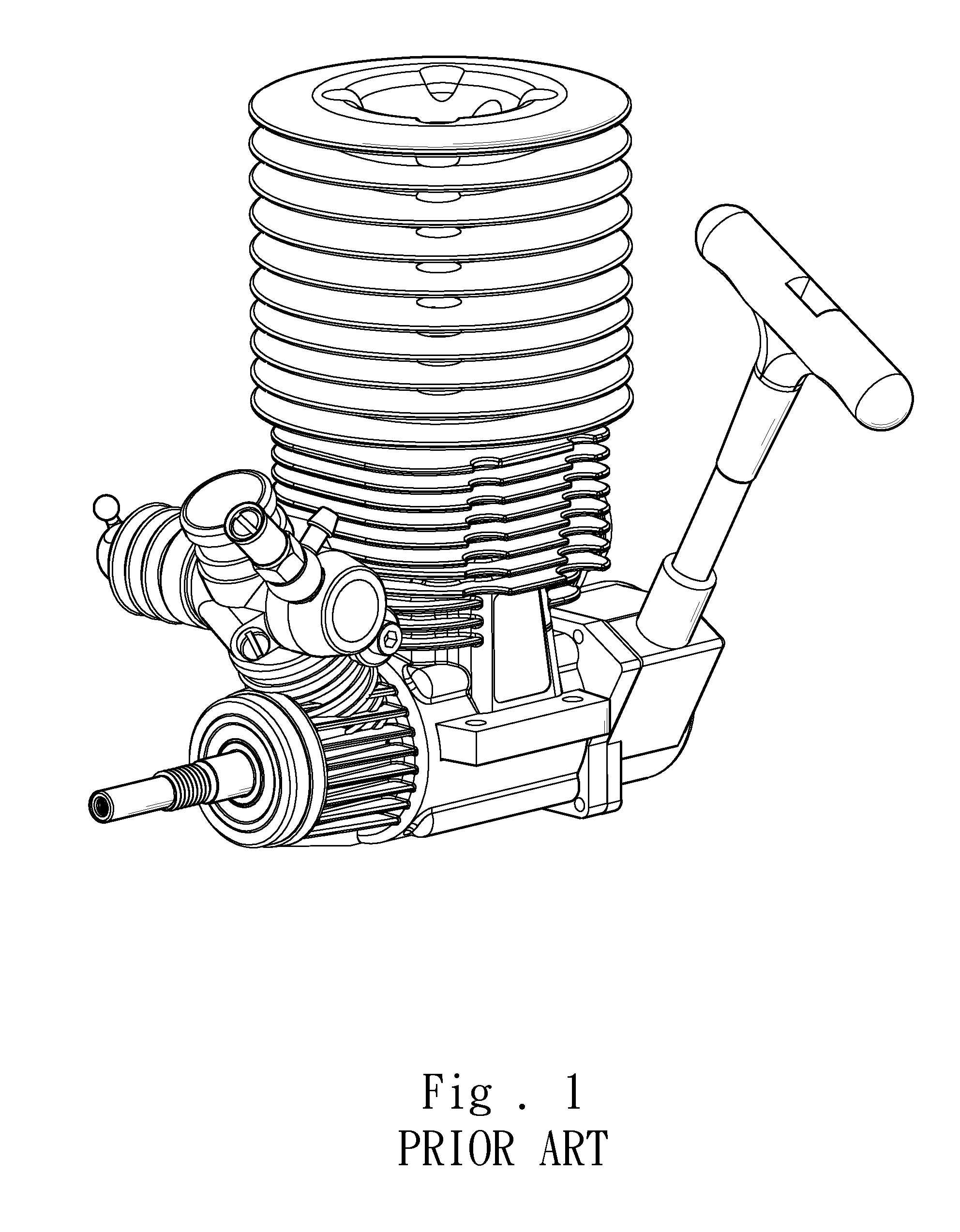
[0015]The engine 10 is installed on a model toy, such as a model toy car or a model airplane.

[0016]The radiator 20 is arranged on the engine 10. The radiator 20 is a hollow body and has a plurality of fins 21 on the surface thereof. The top of the radiator 20 has a cover 22, and the cover 22 has four screws 23. The screws 23 pass through the body of the radiator 20 and fasten the radiator 20 to the engine 10. The top of the radiator 20 also has a water outlet 24 and a water inlet 25. A tube 26 extends from below the water outlet 24 to an appropriate depth inside the radiator 20. Water is filled into the radiator 20 to about 80% capacity.

[0017]One end of the pipe 30 is connected with the water outlet 24 of the radiator 20, and the other end is connected with the water inlet 25 of the ra...


PUM


Abstract

A water cooling device for a model toy engine comprises an engine, a radiator, a pipe, a cooler, and a water tank. The radiator is fixedly installed on the engine. The radiator contains water and has a water outlet and a water inlet on the top thereof. A pipe interconnects the water outlet and the water inlet. A cooler and a water tank are installed to connect with the pipe. The heat generated by the engine boils the water inside the radiator into vapor. The vapor flows into the pipe, and the cooler cools the vapor into water, and then the condensed water flows back to the radiator. The cooling cycle is repeated persistently to dissipate the heat generated by the engine. Therefore, the present invention can cool the engine without using any motor or pump. Further, the present invention can prevent the engine from overheat or burnout, avoid horsepower falling, and prolong the lifetime of the engine.

Description

FIELD OF THE INVENTION[0001]The present invention relates to model toy engines, particularly to a water cooling device for a vehicle model toy engine, which can keeps the engine temperature within a specified range.BACKGROUND OF THE INVENTION[0002]Refer to FIG. 1. The conventional model toy engine does not use a water cooling device but dissipates heat by the thermal conduction between the fins and the air flowing through the fins in movement. The model toys usually operate at a high speed, and the temperature of the operating model toy engines will rise rapidly. When a model toy is still accelerated at a temperature of over 200° C., the horsepower of the engine will fall gradually. When an engine operates at a high speed for a long time, the engine body and the components will be distorted or even burnt out. Therefore, the engine had better operate at a temperature of between 120° C. and 160° C.—a safety temperature range that will not decrease power output. In a common automobile,...

Claims


Application Information

Patent Timeline
IPC IPC(8): F01P5/10
CPCF01P2070/52F01P3/22
Inventor LO, MAO-SHENG
Owner LO MAO SHENG
Why Eureka
Try Eureka