Backlight device and liquid crystal displaying device

Inactive Publication Date: 2010-03-04
SHARP KK
View PDF9 Cites 5 Cited by
  • Summary
  • Abstract
  • Description
  • Claims
  • Application Information

AI Technical Summary

Benefits of technology

[0031]According to the present invention, it is possible to realize frame narrowing by a technically reasonable design, without technical limitation for frame narrowing which tends to be considered troublesome when bent-tube type fluorescent tubes having U-shaped or channel-shaped bent portions are alternately arranged to face each other nor without the trouble accompanied with the work of storing the bent-tube type fluorescent tubes in a chassis, which becomes a problem in manufacturing.
[0032]Furthermore, according to the present invention, it is possible to uniform distribution of luminance or chromaticity in the whole screen of a larger-sized screen while securing safety in a high-voltage wiring processing with much less number of components such as an inverter transformer.

Problems solved by technology

In addition, due to stray capacitance between the fluorescent tube and a unit accompanied with that, leak currents are likely to be generated near a high-voltage portion.
As a result, the temperature difference in the tube axis direction of the fluorescent tube becomes large.
Further, due to the above-described generation of the leak currents, the fluorescent tube is lit with a total current value of rated currents and leak currents near the high-voltage portion of the fluorescent tube, which causes luminance difference generated in the tube axis direction of the fluorescent tube.
In this way, with enlargement of the backlight, the temperature difference and the luminance difference in the tube axis direction of the fluorescent tube are likely to be increased, which has caused generation of luminance unevenness of the backlight.
At this time, as a length of the glass tube is made longer, it becomes difficult to obtain uniform distribution of three colors of phosphors.
When the distribution of three colors of phosphors becomes uneven in the tube axis direction of the glass tube, difference is generated in the capability that the phosphors convert ultraviolet rays into visible light or rates that the phosphors absorb the visible light, thus generating color unevenness and luminance unevenness in the tube axis direction of the glass tube.

Method used


Image

  • Backlight device and liquid crystal displaying device
  • Backlight device and liquid crystal displaying device
  • Backlight device and liquid crystal displaying device

Examples


Embodiment Construction

[0055]With reference to the accompanied drawings, preferred embodiments of a backlight device of the present invention will hereinafter be described. Note that, in all of the figures illustrating the embodiments, same reference numeral is given to any portion having the similar function, with repeated description thereof omitted.

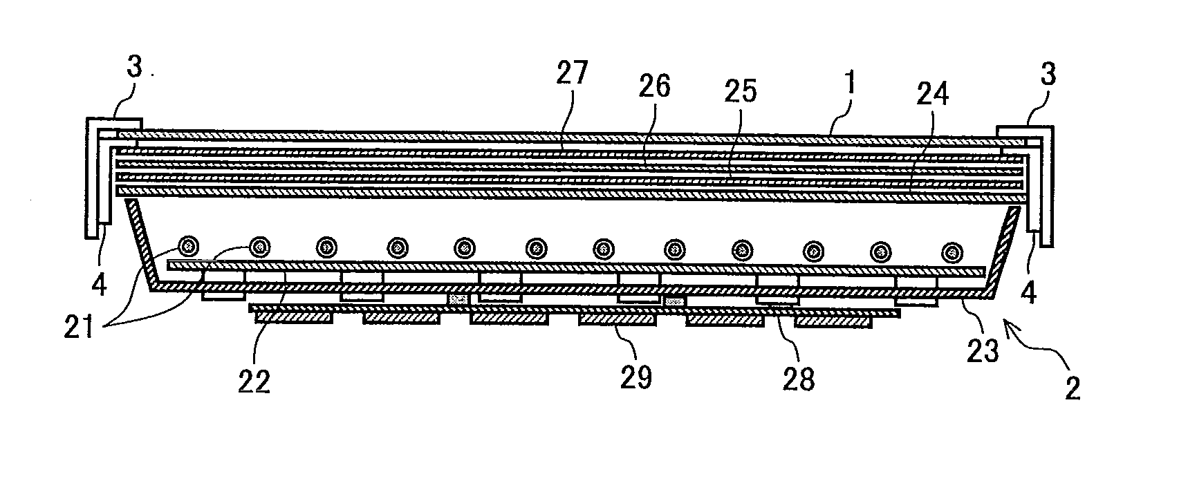
[0056]FIG. 1 is a sectional view showing a structural example of a liquid crystal displaying device using the backlight device according to the present invention. The liquid crystal displaying device includes a liquid crystal panel 1 and a backlight device 2, as the primary structure.

[0057]The liquid crystal panel 1 feeds a video signal to which a video signal processing is applied as a predetermined gradation voltage for each pixel in accordance with a clock signal of the liquid crystal panel 1, and successively applies a video display processing by scanning on a screen to thereby display a video in accordance with the video signal. The liquid crystal panel...


PUM


Abstract

A frame is narrowed by a technically reasonable design, without technical limitation for frame narrowing which tends to be considered troublesome when bent-tube type fluorescent tubes having U-shaped bent portions are to be alternately arranged to face each other nor without the trouble of storing the bent-type fluorescent tubes in a chassis while being manufactured. A backlight device (2) is provided with a backlight chassis (23) wherein a plurality of fluorescent tubes (21) having electrodes are arranged and stored, and an inverter circuit board is arranged on the rear surface of the backlight chassis (23). Furthermore, the backlight device (2) is provided with a storing section (30), which is attached to the backlight chassis (23) by storing a conductive holding section for holding the electrodes. With the storing section (30) attached to the backlight chassis (23), the electrodes of the fluorescent tubes (21) are electrically connected to a light source lighting circuit board arranged on the rear surface of the backlight chassis (23).

Description

TECHNICAL FIELD[0001]The present invention relates to a backlight device and a liquid crystal displaying device, more specifically, to a backlight device that is used as a light source for illumination, such as a liquid crystal television and a liquid crystal displaying device including the backlight device.BACKGROUND OF THE INVENTION[0002]With enlargement of a screen of a liquid crystal television or the like in recent years, enlargement of a backlight included in the liquid crystal television is also required. In order to cope with such a requirement for enlargement of the backlight, and further with a requirement for energy saving, price reduction and the like, a backlight including a bent-tube type fluorescent tube instead of a conventional straight-tube type fluorescent tube has been developed. Such a bent-tube type fluorescent tube is obtained by bending a substantially center part of a long straight-tube type fluorescent tube and molding the bent portion in a U-shape or in a ...

Claims


Application Information

Patent Timeline
IPC IPC(8): G02F1/13357G09F13/04
CPCG02F1/133604H01R33/02G02F2001/133612G02F1/133608G02F1/133612
Inventor SHIMIZU, MASAKIMORIYASU, MITSUHIRO
Owner SHARP KK
Why Eureka
Try Eureka