Motor-driven steering lock apparatus
a technology of motor-driven steering and locking apparatus, which is applied in the direction of electrical locking circuit, anti-theft devices, lock applications, etc., can solve the problems of internal cpu failure to start, circuit structure to become complicated, internal cpu production of improper operation, etc., to achieve secure safety and reliability, simplify control circuit, and high safety
- Summary
- Abstract
- Description
- Claims
- Application Information
AI Technical Summary
Benefits of technology
Problems solved by technology
Method used
Image
Examples
first embodiment
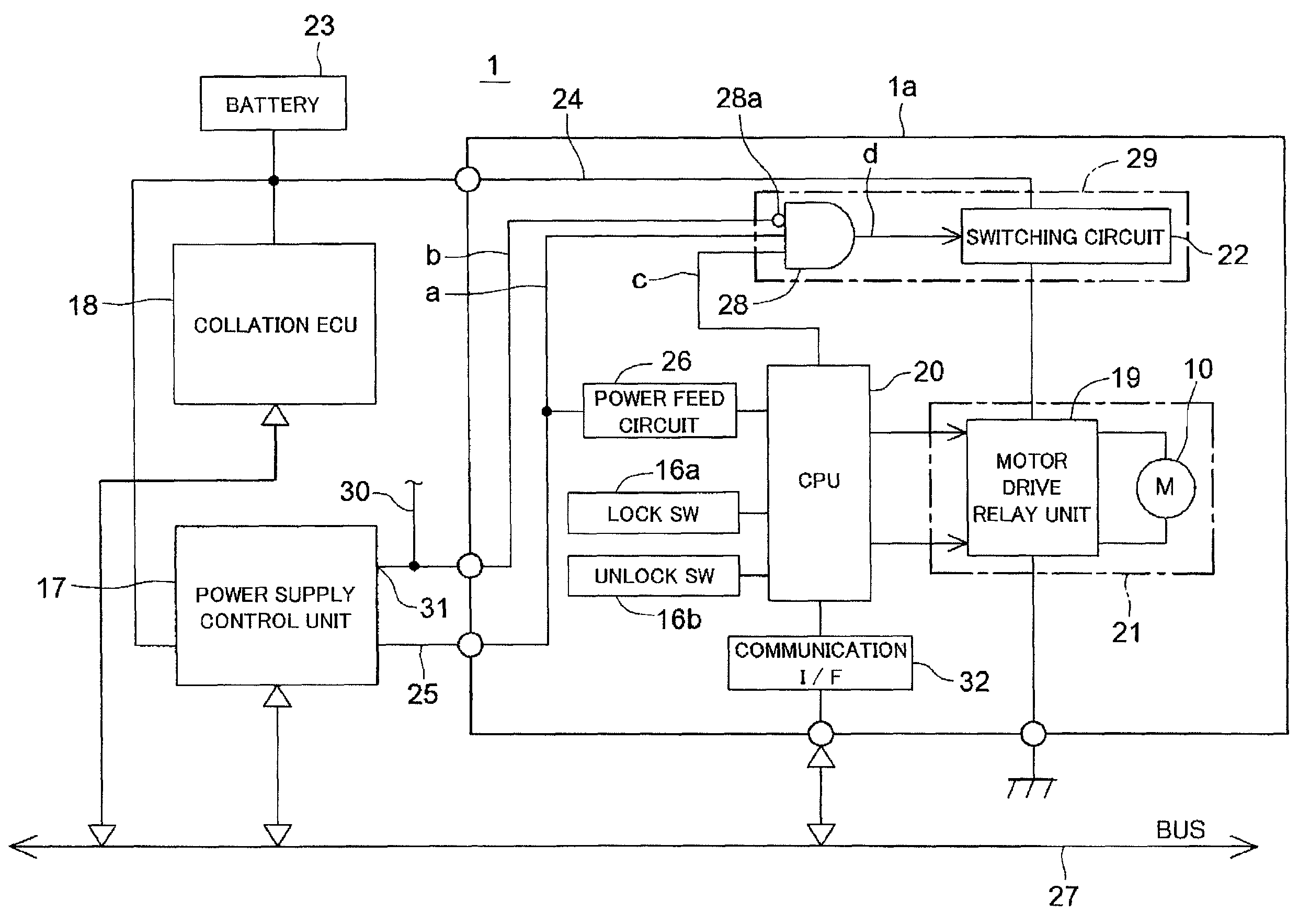
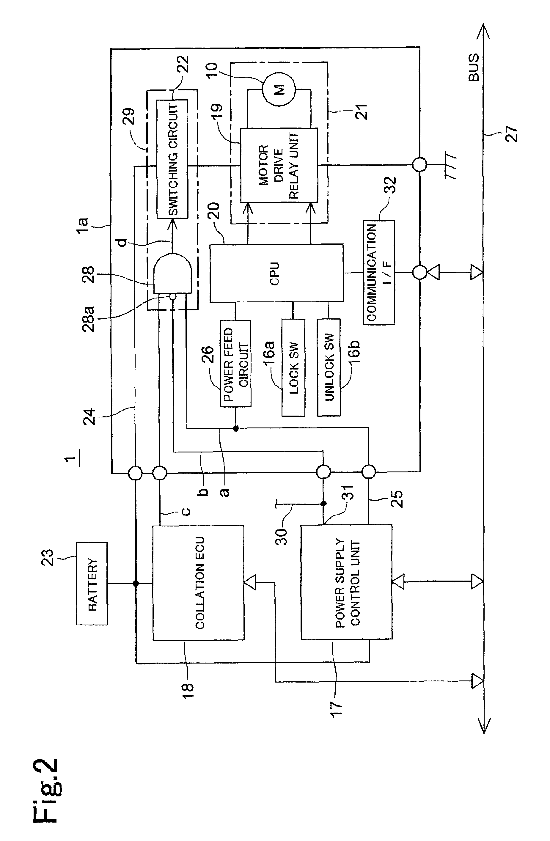
[0023]FIG. 2 shows a circuit diagram of the motor-driven steering lock apparatus 1 in accordance with a The motor-driven steering lock apparatus 1 has a motor-driven steering lock apparatus main body la, a power supply control unit 17 serving as a host first control means, and a collation ECU 18 serving as a host second control means.
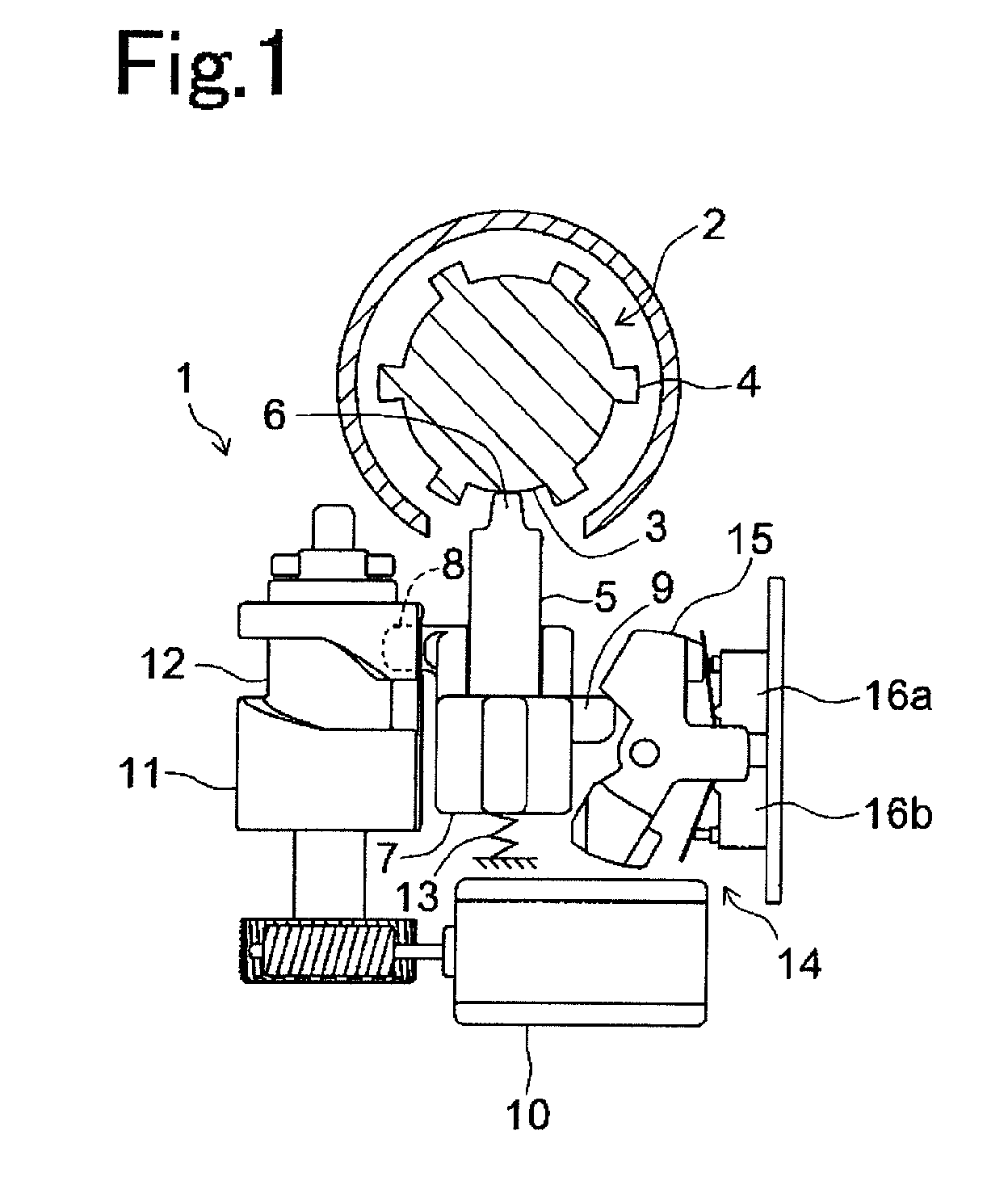
[0024]The motor-driven steering lock apparatus main body la has an electric motor 10 driving the lock bolt 5, a motor drive relay circuit 19 feeding a power supply to the electric motor 10 so as to drive it, and a CPU 20 controlling the motor drive relay circuit 19 and serving as a drive control means in accordance with the present invention. The electric motor 10 and the motor drive relay circuit 19 construct a drive unit 21 serving as a driving means in accordance with the present invention.
[0025]An electric power is fed to the motor drive relay circuit 19 from a battery 23 via a switching circuit 22 through a power supply line 24. The motor drive re...
second embodiment
[0053]In the second embodiment, when the CPU 20 receives the unlock demand signal from the power supply control unit 17 at a time of starting the engine, the CPU 20 outputs the “motor power supply control signal on” to the AND circuit 28 via the signal line c. Further, the “ESL power supply on” and “IG power supply off” signals are output to the AND circuit from the power supply control unit 17, the AND circuit 28 outputs the on signal to the switching circuit 22. Accordingly, the switching circuit 22 turns on, and the power supply is fed to the electric motor 10 from the battery 23. After completing the unlock operation, the CPU 20 turns off the “motor power supply control signal”. Further, when the CPU 20 receives the lock demand signal from the power supply control unit 17 at a time of stopping the engine, the CPU 20 outputs the “motor power supply control signal on” to the AND circuit 22 via the signal line c, and turns off the “motor power supply control signal” after completin...
PUM
 Abstract
Description
Claims
Application Information
 - R&D
- Intellectual Property
- Life Sciences
- Materials
- Tech Scout
- Unparalleled Data Quality
- Higher Quality Content
- 60% Fewer Hallucinations
Browse by: Latest US Patents, China's latest patents, Technical Efficacy Thesaurus, Application Domain, Technology Topic, Popular Technical Reports.
© 2025 PatSnap. All rights reserved.Legal|Privacy policy|Modern Slavery Act Transparency Statement|Sitemap|About US| Contact US: help@patsnap.com


